Manitowoc Published 07-23-15, Control # 078-03 4-53
31000 LUFFING JIB OPERATOR MANUAL SET-UP AND INSTALLATION
55
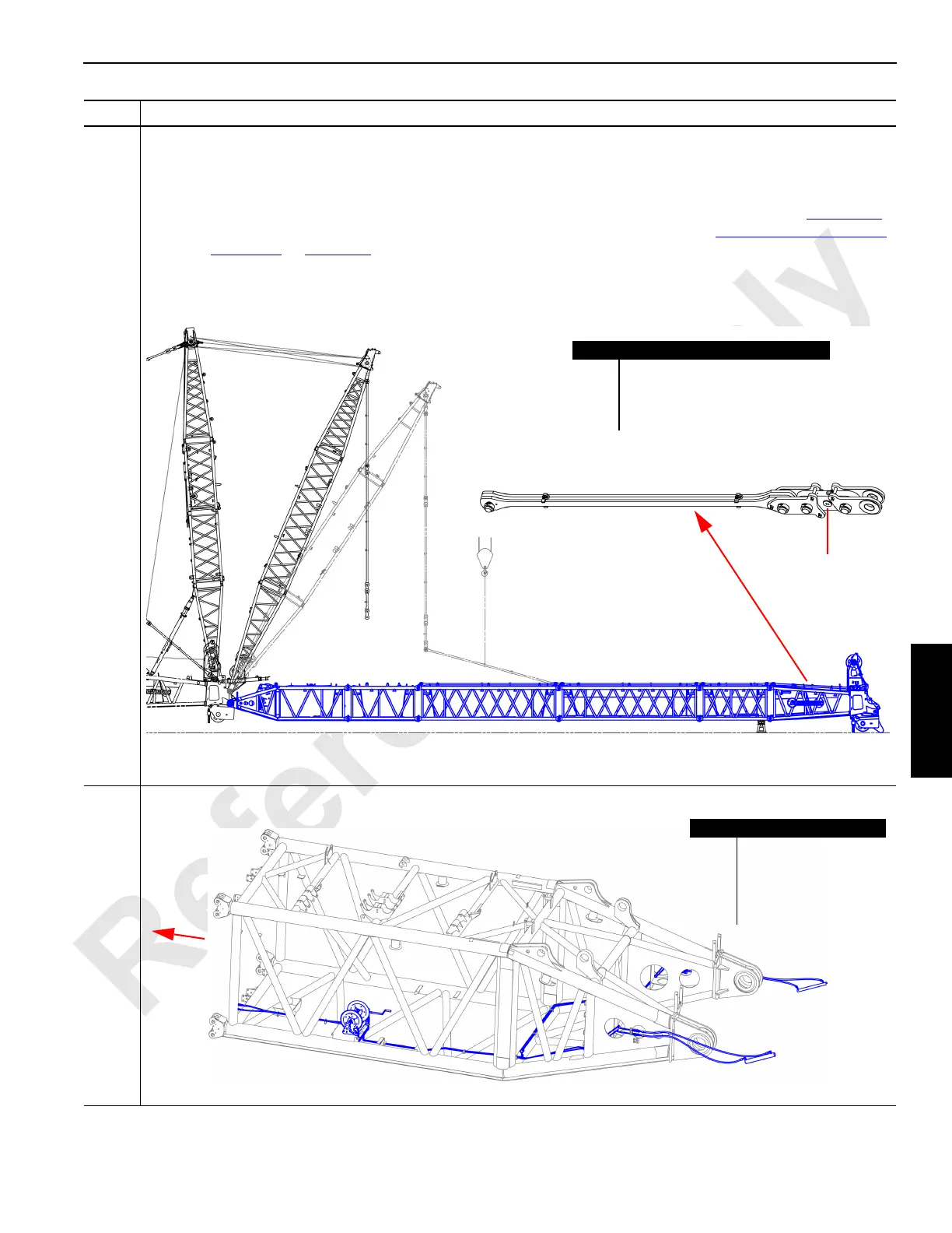
Information below from drawing A19443, Sheet 25:
Complete the jib assembly:
• Use an assist crane to attach each insert (A) and the #91 luffing jib top (B) per drawing A19443.
NOTE: If intermediate suspension shall be installed, then the intermediate suspension yokes (see Figure 4-72
)
shall be installed on the bottom connectors of the appropriate insert. See Intermediate Suspension
Installation on page 4-65.
• See drawing A18701 to connect inserts (A) and #91 luffing jib top (B).
• Connect insert straps (C) per drawing A18701. Note that the strap that connects directly to the #91 luffing jib top
(B) has a load link (D). Refer to the jib backstay table on drawing A19443.
56
• Uncoil the hydraulic lines (A) from the jib butt assembly reel (B) and extend the lines to the #91 luffing jib top (C).
Step Action
FIGURE 4-55
Item Description
A Insert.
B #91 luffing jib top.
C Insert straps.
D Load link.
A
AB
54 m (177 feet) luffing jib length configuration shown
C
A
A
CC
C
D
FIGURE 4-56
Item Description
A Hydraulic lines.
B Jib butt assembly reel.
C Jib top.
D Jib stop assembly
hydraulic cylinder.
A
B
C
D
D

 Loading...


