Manitowoc Published 07-23-15, Control # 078-03 4-57
31000 LUFFING JIB OPERATOR MANUAL SET-UP AND INSTALLATION
60
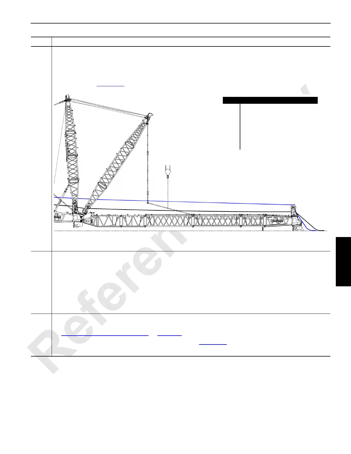
Information below from drawing A19443, Sheet 25:
• Reroute the main load hoist line (A) from the top to the bottom of the wire rope guide (B).
• Tie off the main load hoist line (A) and the whip line (E) to the #91 luffing jib top (C).
• Use an assist crane (D) to lift the last insert strap (F) and attach it to the bottom suspended strap (G) with the pin/
collar/pin from Figure 4-57
.
61
• Connect the electric wiring between the boom and the luffing jib and at the luffing jib points. See Electric Control
Assembly, Boom Wiring and Limits drawing at the end of this section.
If the upper point will not be installed, DO NOT CONNECT the upper point electric cable (WUBP) at the
universal node in the jib point. Faulty operation and system faults will occur.
• Install the wind speed indicator and connect the electric wiring. See Wind Speed Assembly drawing at the end of
this section.
• Install the aircraft warning system. See Electrical Accessory Assembly, Aircraft Warning drawing at the end of
this section.
62
• If the #91 luffing jib length is 90 m (295.3 ft) or greater, then intermediate suspension shall be installed. Go to
Intermediate Suspension Installation
on page 4-65.
• If the #91 luffing jib is less than 90 m (295.3 ft), then go to Figure 4-61
.
Step Action
FIGURE 4-60
Item Description
A Main load hoist line.
B Wire rope guide.
C #91 luffing jib top.
D Assist crane.
E Whip line.
F Last insert strap.
G Bottom suspended strap.
D
A
B
C
E
F
G