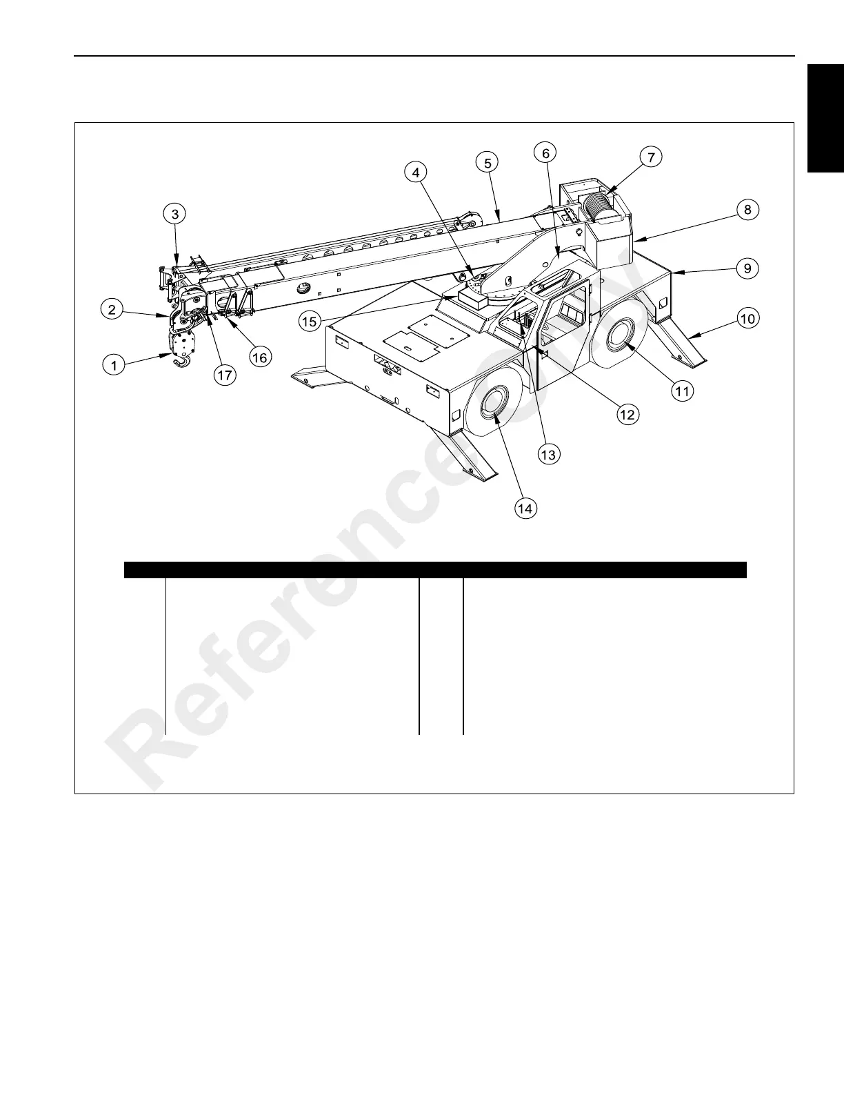
EasyManuals Logo
Home>Manitowoc>Construction Equipment>Grove 5540F

Manitowoc Grove 5540F User Manual

Manitowoc Grove 5540F
134 pages
To Next Page IconTo Next Page
To Previous Page IconTo Previous Page
Page #13 background imageLoading...
Page #13 background image
GROVE Published 10-21-2011, Control # 055-03 1-3
5540F/YB5515 OPERATOR’S MANUAL INTRODUCTION
1
NOMENCLATURE
FIGURE 1-2
Item Description Item Description
1 Drop Block 10 Outrigger (4)
2 3rd Boom Section (3 Section Boom)
4th Boom Section (4 Section Boom)
11 Rear Drive Axle (Steerable & Non-Steerable)
12 Enclosed Operator’s Cab (Shown)
Optional Cab Guard (Not Shown)3 Optional Boom Extension
4 Lift Cylinder 13 Main Control Valve Location
5 1st Boom Section 14 Front Steering Drive Axle
6 Engine Compartment 15 Swing Motor and Gearbox Location
7 Main Hoist Assembly 16 2nd Boom Section
8 Mast Assembly 17 3rd Section Boom
9 Main Frame Assembly
a1841
Reference Only

Table of Contents

Other manuals for Manitowoc Grove 5540F

Questions and Answers:

Question and Answer IconNeed help?

Do you have a question about the Manitowoc Grove 5540F and is the answer not in the manual?

Manitowoc Grove 5540F Specifications

General IconGeneral
BrandManitowoc
ModelGrove 5540F
CategoryConstruction Equipment
LanguageEnglish

Related product manuals