19
20
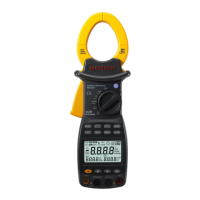
4.10 Current Measurement
1) Rotary switch is placed to position A. At this time,
the meter is in AC current measurement state.
Choose appropriate measuring range. If you want
to measure DC current, press FUNC button to enter
direct current measurement state.
2) Hold the trigger, open clamp head, clip one lead of
measurement circuit to be tested in the clamp.
3) When measuring AC current, the main display
shows measured value, and the alternate display
shows the frequency of the current to be measured.
4) Read the current value on the LCD display.
Note:
4.11 Voltage Measurement
1) Clamping two or more leads of circuit to be tested
simultaneously will not give correct measuring results.
2) To get accurate readings, connect the lead to be
tested at the center of current clamp.
4) To improve the measurement precision, in the DC
current measurement state, if the LCD display is not
zero, press ZERO to return to zero, then measure.
5) When measuring current, be sure to switch the
meter to DC or AC state first, then clamp the wire to
be measured in the clamp. Otherwise, it will cause
invalid readings.
1) Insert black probe to COM jack, insert red probe to
INPUT jack, choose appropriate measuring range.
2) Place transfer switch to AC voltageV position.
At this time, the meter is in the AC voltage
measurement state. To measure DC voltage, press
FUNC button to enter DC voltage measurement state.
3) To measure mV voltage, switch the meter to mV
range through the RANGE key.
4) Connect the probe with voltage source or both ends
of load in parallel for measurement.
5) Read the voltage on the LCD.
Note:
1) In the small voltage measuring range, the probe is
not connected with the circuit to be tested, and the
meter may have fluctuating readings. This is normal
and caused by the meter's high sensitivity. When
the meter is connected with the circuit to be tested,
you will get actual measured value.
4.12 Frequency and Duty Ratio Measurement
1) Insert black probe to COM jack, insert red probe to
INPUT jack.
2) Transfer switch is placed to position HZ.
3) Connect the probe with signal or both ends of load
in parallel for measurement.
Note:
Frequency measurement range is 10Hz~60MHz. If
the frequency to be tested is less than 10Hz, LCD will
show “00.0”. When measuring frequencies higher than
60MHz, duty ratio measurement accuracy is not
guaranteed.
 Loading...