62
9.10 DRIVE SET REPLACEMENT - CONTINUED
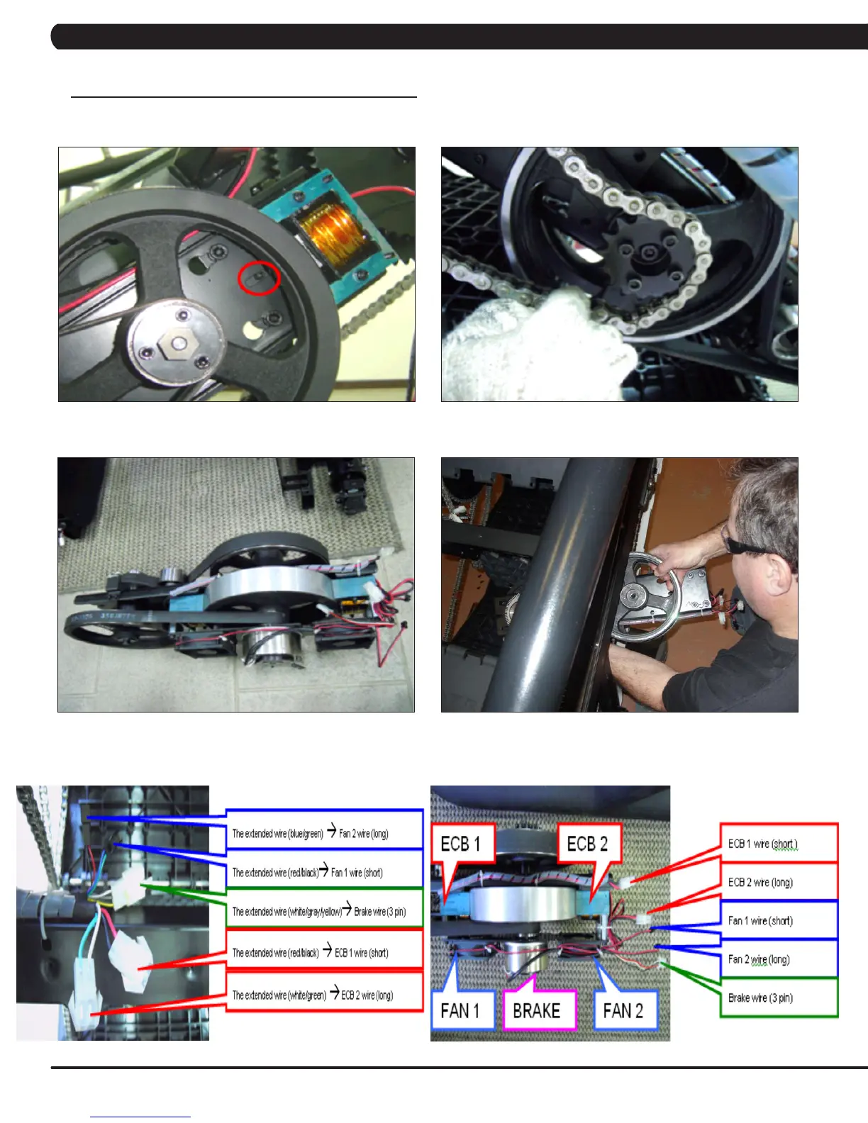
9) While a tech is pushing the drive set towards the front of the unit (the drive set will still be supported by the guide screw - Figure G), the other
tech should remove the chain from the sprocket simultaneously (Figure H). You can also remove the sprocket to remove the chain if easier.
10) Remove the drive set from the unit (Figure I). NOTE:Thedriveaxlewillneedtoberotatedsothatthepulleysarehorizontaltotthrough
the side covers (Figure J).
11) Reverse Steps 1-10 to install a new drive set. NOTE: Make sure that the wiring disconnected in Step 5 gets connected correctly. Refer to
Figures K & L. NOTE: Torque the bolts removed in Step 7 to 40N-m.
12) Test the Climb Mill for function as outlined in Section 9.20.
FIGURE HFIGURE G
CHAPTER 9: PART REPLACEMENT GUIDE
FIGURE I
FIGURE LFIGURE K
FIGURE J
 Loading...