Disassembly Procedures
To avoid the risk of electrical shock, personal injury or
death; disconnect power to oven and discharge
capacitors before following any disassembly procedure.
WARNI NG
!
16026268 26 ©2005 Maytag Services
Transformer
Power Transformer Removal
1. Disconnect power to unit and remove outer case, see
"Outer Case" procedure.
2. Discharge high voltage capacitor, see "High Voltage
Capacitor" procedure.
3. Disconnect and label wire leads from transformer.
4. Remove screws securing transformer and remove.
5. Reassemble in reverse order.
Fuse
Fuse Removal
Fuse is located in line with the power cord.
1. Disconnect power to unit and remove outer case, see
"Outer Case" procedure.
2. Remove and replace fuse, reassemble in reverse
order.
CAUTION
!
Before replacing a blown monitor fuse, test the primary
interlock switch, secondary interlock switch, monitor
switch, and power relay contacts for proper operation.
If the monitor fuse is blown by a failed switch operation
all switches and printed circuit board must be
replaced.
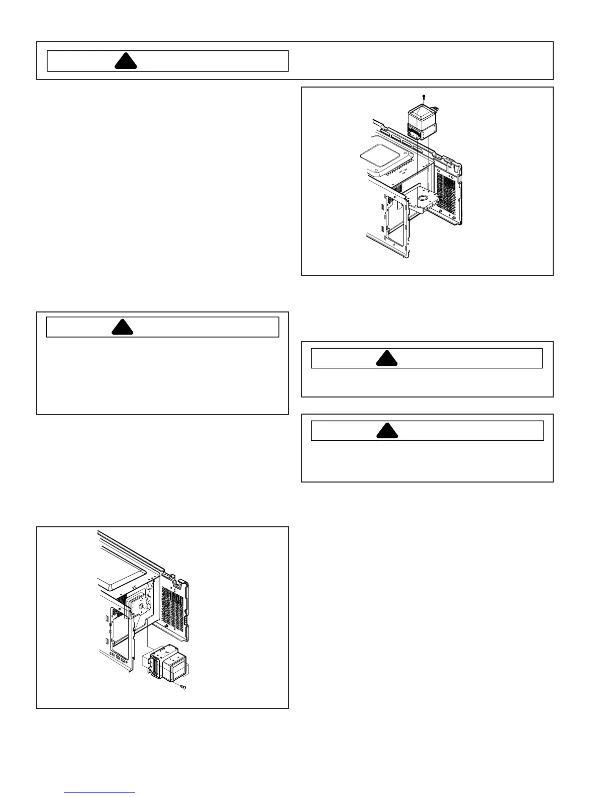
Magnetron
Magnetron is mounted on the side of the cavity.
1. Disconnect power to unit and and remove outer
case, see "Outer Case" procedure.
2. Discharge high voltage capacitor, see "High Voltage
Capacitor" procedure.
3. Remove screws securing magnetron to the wave
guide.
Magnetron
All models except UMC1061*
Magnetron
For model UMC1061* only
4. Reassemble in reverse order.
NOTE: When replacing the magnetron, make sure the
gasket is in the correct position and in good
condition.
CAUTION
!
During replacement of magnetron, be certain the R.F.
anode gasket is in place around the anode stud.
WARNI NG
!
A microwave leakage test must be performed anytime
a magnetron assembly is removed, replaced,
disassembled, or adjusted for any reason.
Suction Guide / Fan Motor Assembly
Suction guide assembly also consists of the latch board
assembly.
Magnetron fan motor provides cool air circulation from
an external air source, which provides direct cool air
through air vanes surrounding the magnetron.
1. Disconnect power to unit and and remove outer
case, see "Outer Case" procedure.
2. Discharge high voltage capacitor, see "High Voltage
Capacitor" procedure.
3. Disconnect wire leads from fan motor and high
voltage capacitor.
4. Remove screw securing diode to chassis.
5. Remove screws securing suction guide assembly to
the oven cavity.
 Loading...