68 AGR 070A through 100A IOMM AGR-1
Start-Up and Shutdown
Pre-Start Checkout
Configuration default set points are entered at the factory and all values must be checked and reset for
each installation. Make sure the field wiring for all flow switches, interlocks or jumpers matches the
connections detailed on the field wiring drawing.
Setting of the HEX Address Switches
The controller HEX address switches for each unit determine its logical address in a MicroTech
network or in an Open Protocol network. If the chiller is not connected to a RS485 communications
loop, set the address switches as follows: Hi=0; Lo=1.
Network addresses are pre-assigned and will be located in the installation instructions for the
particular network panel.
Control Switches
Before applying power to the unit, verify that the Unit System Switch is in the stop position and that
each Circuit Switch is in the Pumpdown and Stop position. It an optional Remote Start / Stop input is
installed, it should be in the start position.
Ribbon Cables
Check the ribbon cables that connect the keypad, ADI board and output board to the controller. They
should be fully seated with the locking tabs engaged.
Powering the MicroTech Controller
There are three status LEDs located on the model 250 controller which will indicate the controller’s
operating condition. When power is first applied to the control panel through the circuit breaker
(CB), the red RESET LED will illuminate for approximately 3 seconds. During this time, the
controller is checking the control software and performing internal hardware tests. When these tests
are completed, the RESET LED will turn off and the green RUNNING LED will illuminate indicating
the controller’s circuitry and software are operating correctly. If the RESET LED stays on or the
RUNNING LED fails to illuminate, consult the trouble shooting section of the manual.
Any alarms showing should be cleared by pressing the alarm key then the clear key. Watch the LEDs
on the output board and ADI board to determine the operating status of the controller’s inputs and
outputs while performing the following system checks. Initially all LEDs on the output board will be
off.
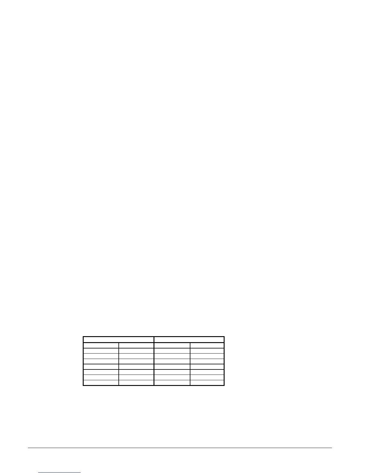
Table 21, Initial Condition ADI board LEDs
DH1 DH2
0ON8ON
1 OFF 9 OFF
2ON10ON
3OFF11OFF
4ON12ON
5OFF13ON
6 ON 14 ** OFF
7ON15ON
** Flow switch may be on if not controlled by the unit controller
Move the system switch to the Auto position. LED #5 on the ADI board will turn on. If the time
schedule is in occupied, the chilled water pump relay output board #2 will turn on.
Move both pumpdown switches to the auto position. DH1-7 and DH2-15 will turn off. The
controller will then activate one of the refrigerant circuit solenoids depending upon which is the lead
circuit (output relay #4 circuit #1or output relay #5 circuit #2). When the evaporator pressure rises
 Loading...


