12 IM710
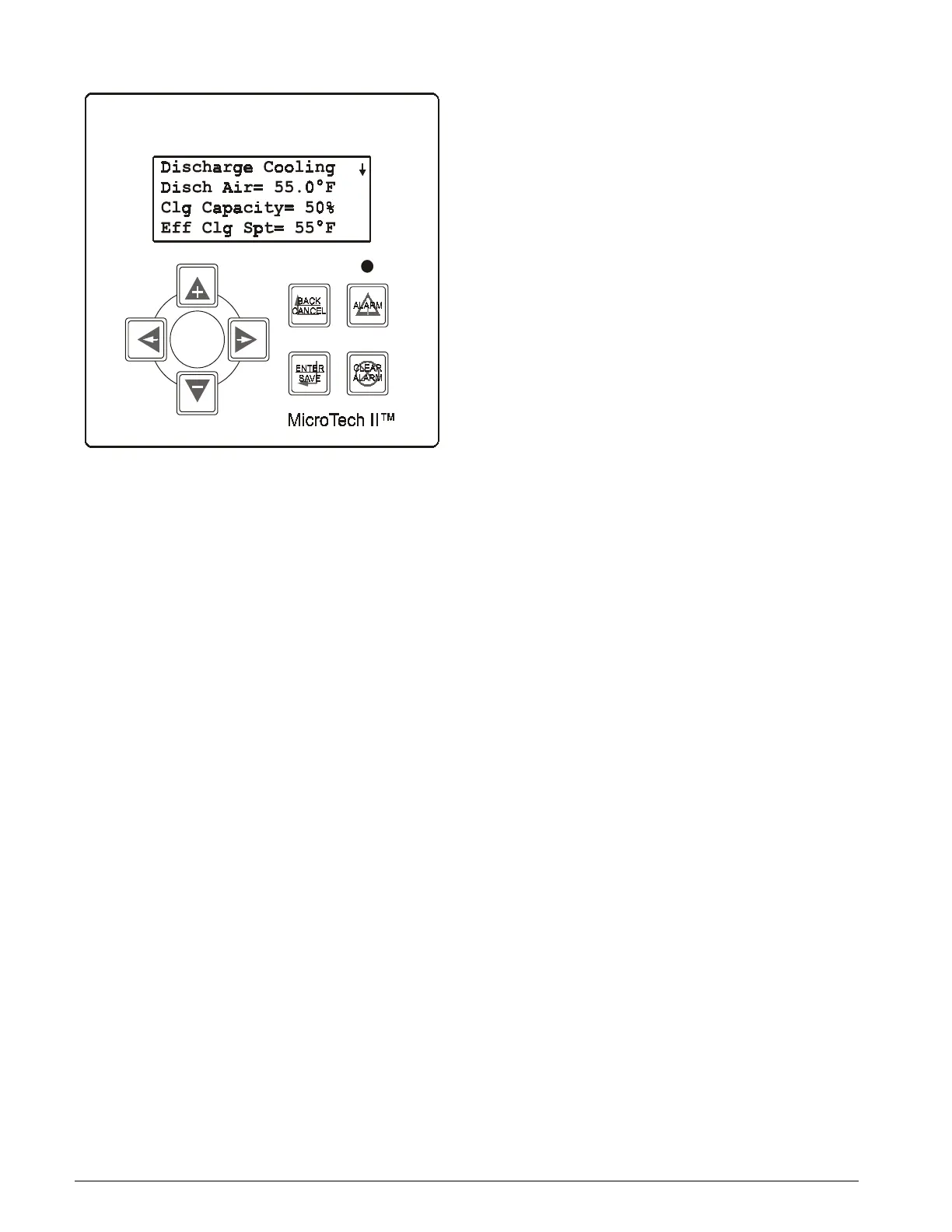
Figure 5: Keypad/Display
Temperature Sensors
The MicroTech II controller uses passive positive tempera-
ture coefficient (PTC) sensors. These sensors vary their input
resistance to the MCB as the temperature changes. Resis-
tance versus temperature information is included in “Trou-
bleshooting Temperature Sensors” on page 47.
Pressure Transducers
The MicroTech II controller uses 0 to 5“ WC, 1 to 6 VDC
static pressure transducers for measuring duct static pres-
sure. If building static pressure control is provided, a -0.25 to
0.25 “WC, 1 to 5 VDC static pressure transducer is used.
Voltage-to-pressure conversion data is included in “Trouble-
shooting Pressure Transducers” on page 48.
Humidity Sensors
The MicroTech II controller uses 0-100% RH, 0-5 VDC
humidity sensors. Refer to “Humidity Sensors” on page 18
for details regarding these sensors.
Actuators
The MicroTech II controller uses floating point (tri-state)
control actuators for valve, damper, and variable inlet vane
modulation.
Non-spring return actuators are used for the condenser,
waterside economizer and heating valves, and inlet vanes. A
non-spring return actuator should be used with the field sup-
plied airside economizer. All valves are normally closed.
The controller senses position feedback from 0-1000 ohm
potentiometers on the waterside economizer, heating, and
inlet vane actuators. The field supplied actuator for the air-
side economizer must have this same feedback. The MCB
uses these feedback signals to determine and display econo-
mizer position and fan capacity, and to display heating
capacity.
Variable Frequency Drives (VFDs)
When controlling the discharge frequency drives, the Micro-
Tech II controller uses floating-point (tri-state) output sig-
nals to modulate the drive speed.
Speed feedback is supplied to the controller via a 0-10 VDC
signal from the VFD. The MCB uses the feedback signal to
determine and display discharge fan capacity.
 Loading...


