20 IM710
Service Information
Controller Inputs
Analog Inputs-Main Control Board (MCB)
The 16 analog inputs to the MCB are configurable for four
different input types by positioning a jumper associated with
each input position (refer to Figure 9). The four jumper posi-
tions are 1-RTD (temperature sensor or potentiometer), 2-
MA (current), 3-NTC (10K ohms thermistor) or no jumper
NJ-VDC (voltage).
Figure 10: Analog Input Jumpers (MCB).
The 1-RTD jumper position is used for all the temperature
sensor inputs and the 0-1000 ohm actuator potentiometer
position feedback inputs. The NJ-VDC (no jumper) position
is used for the remainder of the standard input devices which
are configured for either 0-5 VDC or 0-10 VDC. The 3-NTC
(10K ohm thermistor) jumper positions are not used in this
product application for any of the standard input devices.
The 2-MA jumper position is used when AI-2 on the MCB
for DAT reset with a 0-20mA reset signal. Refer to Table 7
on page 21 (DAC units) and Table 8 on page 22 (SCC units)
for a description of all the analog inputs including the correct
jumper positions.
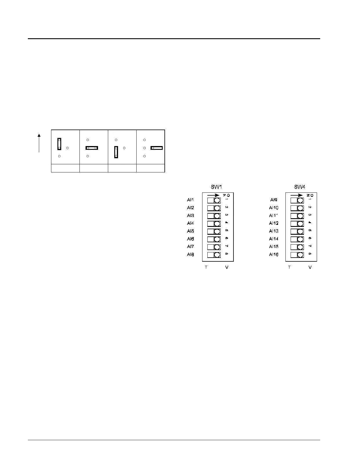
In addition to the analog input jumpers, there are two sets of
dip switches (SW1 and SW4) associated with the MCB ana-
log inputs. Each set contains eight switches numbered 1
through 8. Refer to Figure 10. The switches on SW1 corre-
spond to inputs MCB-AI1 through MCB-AI8 and the
switches on SW4 correspond to inputs MCB-AI9 through
MCB-AI16. One switch corresponds to each analog input. If
the input is a temperature sensor or potentiometer input
(input jumper in the 1-RTD position) then the corresponding
switch must be in the T (OFF) position. If the input is a volt-
age input (no input jumper NJ-VDC position) then the corre-
sponding switch must be in the V (ON) position. Table 7 on
page 21 (DAC units) and Table 8 on page 22 (SCC units)
include the correct switch settings for all the analog inputs.
Note: If a special application requires a current input with
the input jumper set to the 2-MA position, then the
corresponding input switch must be set to the T
(OFF) position.
Figure 11: Analog Input Switches (MCB).
1-RTD 2-MA 3-NTC NJ-VDC
Top
of
MCB
 Loading...


