OM 750 Page 29 of 32
SPACE CO
2
SENSOR FAILURE (OPTIONAL) ( )
The Space CO2 Sensor Failure fault will occur when the UVC detects
an open or a short condition from the Space CO
2
sensor.
Effect:
• CO2 Demand Controlled Ventilation function is disabled
• Fault is indicated
CHANGE FILTER INDICATION ( )
The Change Filter Indication will occur when the UVC calculates that
the total fan run time has exceeded the allowed number of hours since
the last filter change.
Effect:
• Fault is indicated
Troubleshooting Temperature Sensors
The UVC is configured to use passive positive temperature coefficient
(PTC) sensor whose resistance increases with increasing temperature.
The element has a reference resistance of 1035 ohms at 77°F (25°C).
Each element is calibrated according to the tables shown.
The following procedure can be used to troubleshoot a suspect sensor.
1. Disconnect both sensor leads from the UVC.
2. Take a temperature reading at the sensor location.
3.
Use the temperature reading from Step 2 to determine the expected
sensor resistance from the Temperature versus Resistance Table 22.
4. Using an ohmmeter, measure the actual resistance across the two
sensor leads.
5. Compare the expected resistance to the actual resistance.
6. If the actual resistance value deviates substantially (more than
10%) from the expected resistance, replace the sensor.
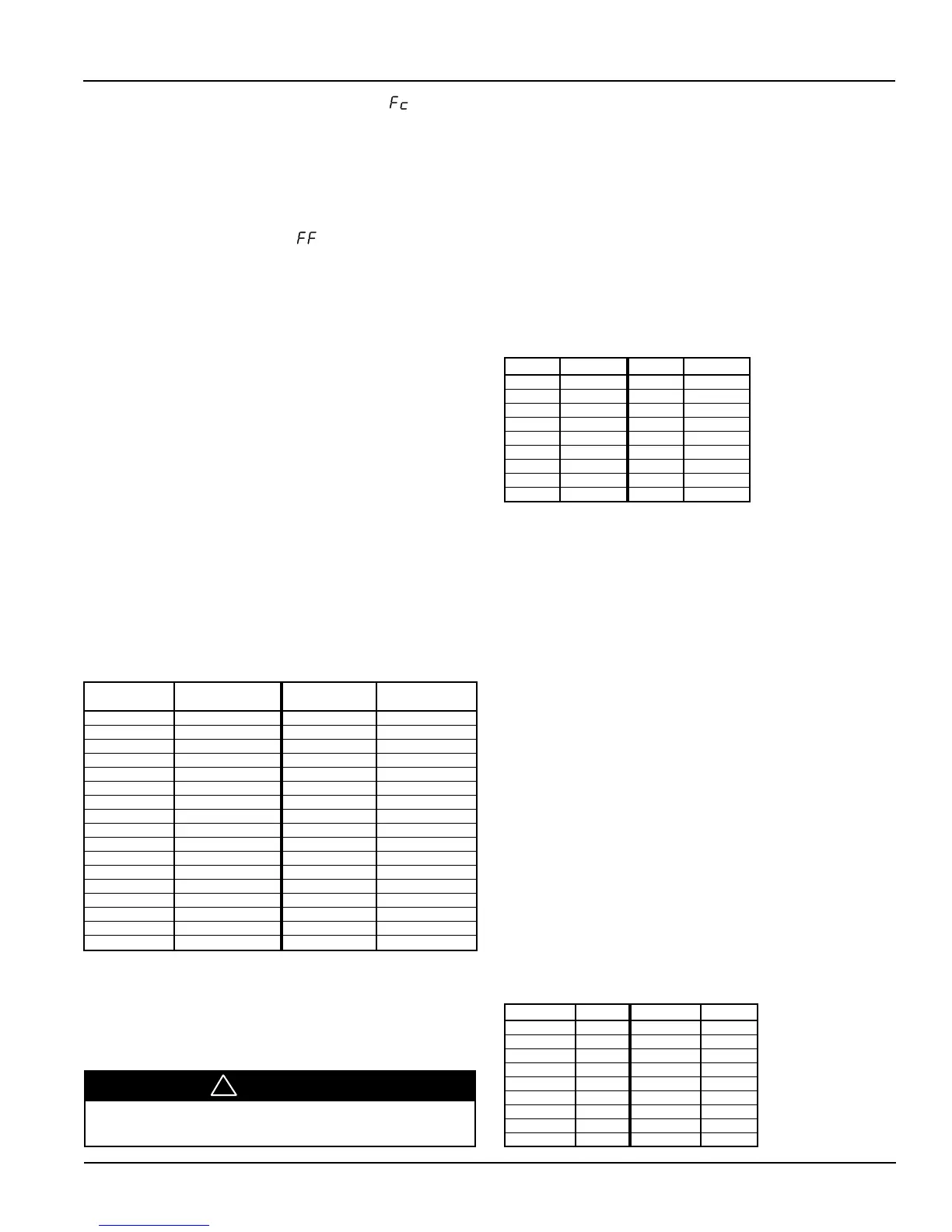
Table 22. Temperature versus Resistance Table
O
F (
O
C)
Resistance
O
F (
O
C)
Resistance
in Ohms
O
in Ohms
-40 (-40) 613 113 (45) 1195
-31 (-35) 640 122 (50) 1237
-22 (-30) 668 131 (55) 1279
-13 (-25) 697 140 (60) 1323
-4 (-20) 727 149 (65) 1368
5 (-15) 758 158 (70) 1413
14 (-10) 789 167 (75) 1459
23 (-5) 822 176 (80) 1506
32 (0) 855 185 (85) 1554
41 (5) 889 194 (90) 1602
50 (10) 924 203 (95) 1652
59 (15) 960 212 (100) 1702
68 (20) 997 221 (105) 1753
77 (25) 1035 230 (110) 1804
86 (30) 1074 239 (115) 1856
95 (35) 1113 248 (120) 1908
104 (40) 1153
Troubleshooting Humidity Sensors
The UVC is configured to use 0-100% RH, 0-5 VDC, capacitive
humidity sensors. Each sensor is calibrated according to the table
shown.
/!\ Caution
The humidity sensor is not protected against reversed polarity. Check
carefully when connecting the device or damage will result.
CAUTION
!
The following procedure can be used to troubleshoot a suspect humidity
sensor.
1. Disconnect the sensor(s)’ output voltage lead from the UVC analog
input.
2. Take a humidity reading at the sensor location.
3. Use the humidity reading from Step 2 to determine the expected
sensor voltage from the Humidity versus Voltage Table 23.
4. Using a multi-meter, measure the actual voltage across the yellow
and white sensor leads.
5. Compare the expected voltage to the actual voltage.
6. If the actual voltage value deviates substantially (more than 10%)
from the expected voltage, replace the sensor.
Table 23. Humidity versus Voltage Table
RH (%) VDC (mV) RH (%) VDC (mV)
10 1330 55 2480
15 1475 60 2600
20 1610 65 2730
25 1740 70 2860
30 1870 75 2980
35 1995 80 3115
40 2120 85 3250
45 2235 90 3390
50 2360 95 3530
Troubleshooting Carbon Dioxide (CO
2
)
Sensors
The UVC is configured to use 0-2000 PPM, 0-10 VDC, single beam
absorption infrared gas sensor. Each sensor is calibrated according to
the table shown.
The following procedure can be used to troubleshoot a suspect sensor.
1. Disconnect the sensor(s)’ output voltage lead from the UVC analog
input.
2. Take a CO
2
reading at the sensor location.
3. Use the CO
2 reading from Step 2 to determine the expected sensor
voltage from the CO
2
versus Voltage Table 24.
4. Using a multi-meter, measure the actual voltage across the lead
removed from xAI-3 and ground.
5. Compare the expected voltage to the actual voltage.
6. If the actual voltage value deviates substantially (more than 10%)
from the expected voltage, replace the sensor.
In the unlikely event that the CO
2
sensor requires calibration, consult
the factory for information on obtaining calibration equipment and
instructions.
Table 24. CO
2
versus Voltage Table
CO
2
(PPM) VDC (V) CO
2
(PPM) VDC (V)
300 1.5 1200 6.0
400 2.0 1300 6.5
500 2.5 1400 7.0
600 3.0 1500 7.5
700 3.5 1600 8.0
800 4.0 1700 8.5
900 4.5 1800 9.0
1000 5.0 1900 9.5
1100 5.5 2000 10.0
DIAGNOSTICS AND SERVICE (continued)

 Loading...


