Engine cooling
Cooling and lubrication
41
Introduction of the New V12 Biturbo Engine, M 279 AMG
b
In order to guarantee the maximum engine power,
the engine and turbochargers must be properly
cooled.
The engine oil cooler (oil/air heat exchanger) is
located in the center
behind the front spoiler. Air
ducting provides optimum air flow and cooling
output. The warm waste air flows through an
opening in the underfloor paneling directly into the
atmosphere.
An additional engine oil cooler with fan is installed
in the righ
t front wheel arch.
The interbore bridges between the cylinders in the
crankcase
have three bores for cooling: two feed
bores that
supply coolant to the bridge, and one
drain bore. The coolant flows out of the bridge via
the bore in the cylinder head. Here there is one feed
bore for each interbore bridge.
Coolant temperature regulation
The coolant temperature is regulated by the ME-SFI
control unit on the basis of the following sensors
and signals:
• Coolant temperature sensor
• Charge air temperature sensor
• Pressure sensor downstream of throttle valve,
engine load
• Accelerator pedal sensor
• Crankshaft Hall sensor, engine speed
• Temperature sensor in ME-SFI control unit
• Front SAM control unit with fuse and relay
mo
dule, out
side air temperature
• Instrument cluster, vehicle speed
• Electronic Stability Program control unit, wheel
speed
• Fully integrated transmission control controller
unit, status of transmission oil temperature
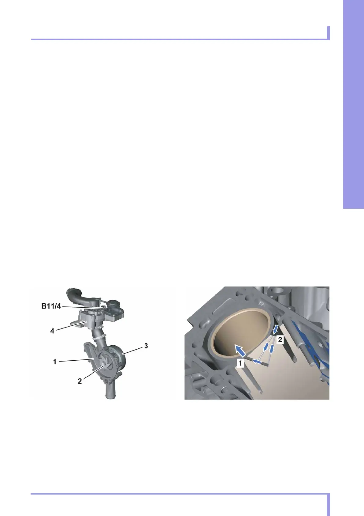
P20.10-2353-00 P20.00-2446-00
Coolant pump Interbore cooling
1Housing
2 Rotor
3 Belt pulley
4Coolant thermostat
B11/4 Coolant temperature sensor
1
Drain bore (to cylinder head)
2 Feed bore
– This printout will not be recorded by the update service. Status: 06 / 2012 –
 Loading...