WIRING DIAGRAMS
90-855347R1 JANUARY 1999 Page 2D-7
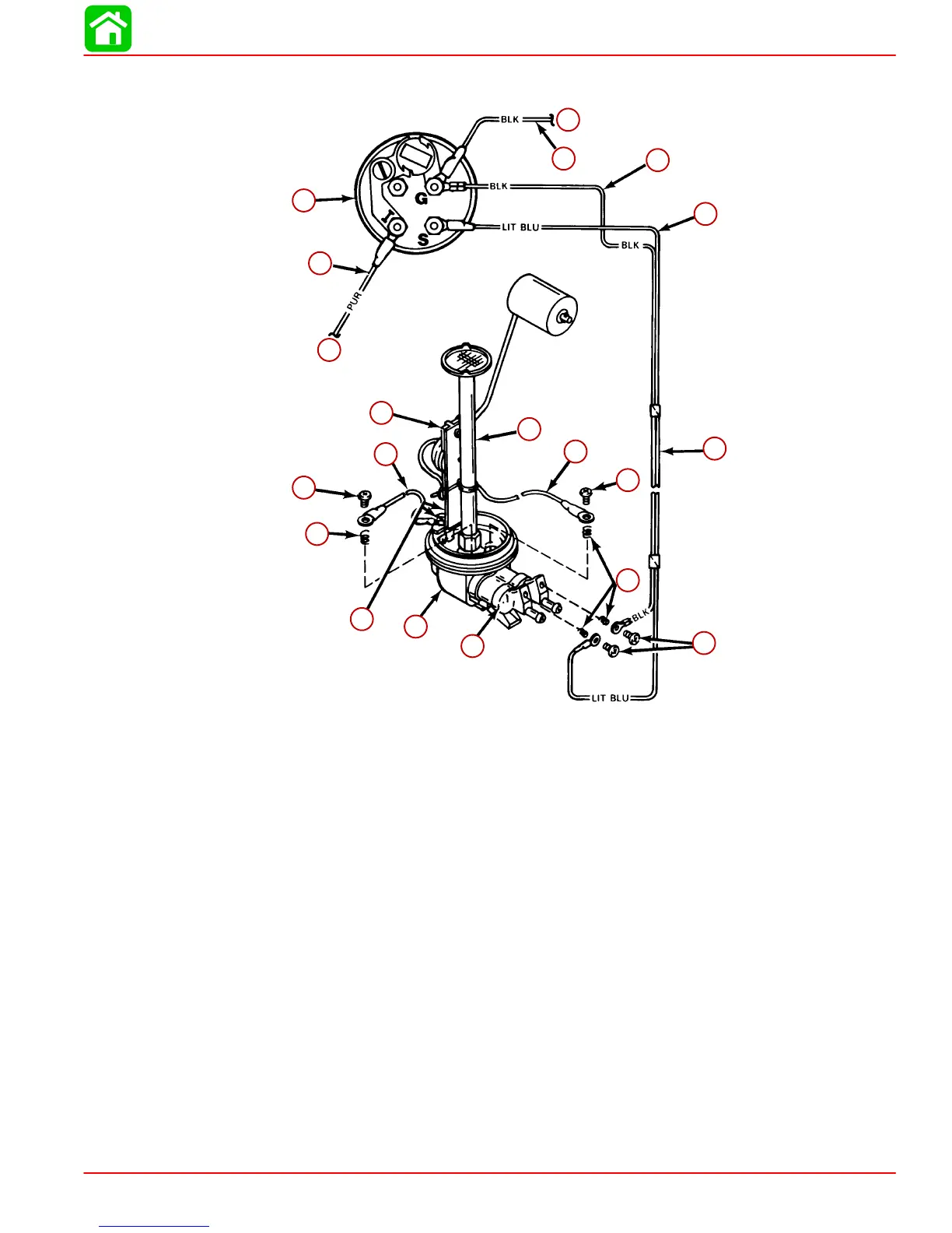
Oil Level Gauge Wiring Diagram
a
b
c
i
o
m
n
j
k
l
h
g
f
p
q
r
s
t
e
d
a
b
c
d
e
f
g
h
i
j
k
l
m
n
o
p
q
r
s
t
a-To 12 Volt Source
b-PURPLE Wire (Connect to Trim Indicator Gauge “I” [or POSITIVE (+) 12 Volt
Source that is Turned “ON” and “OFF” with Ignition Switch])
c-Oil Level Gauge
d-BLACK Wire (Connects to NEGATIVE Ground)
e-To Ground
f-BLACK Wire (From Gauge to Oil Clip Connector)
g-LIGHT BLUE Sender Lead to Gauge
h-Wiring Harness (LT. BLU. and BLACK)
i-Screw (10-16 x 5/8 in.)
j-Spring
k-Oil Clip Connector
l-Adaptor Housing
m-Screw (10-16 x 1/4 in.)
n-Spring
o-Screw (10-16 x 5/8 in.)
p-BLACK Wire
q-Oil Level Sender Unit
r-Oil Pick-Up Tube
s-WHITE Lead (from Oil Level Sender)
t-Screw (10-16 x 5/8 in.)

 Loading...


