WIRING DIAGRAMS
Page 2D-22 90-855347R1 JANUARY 1999
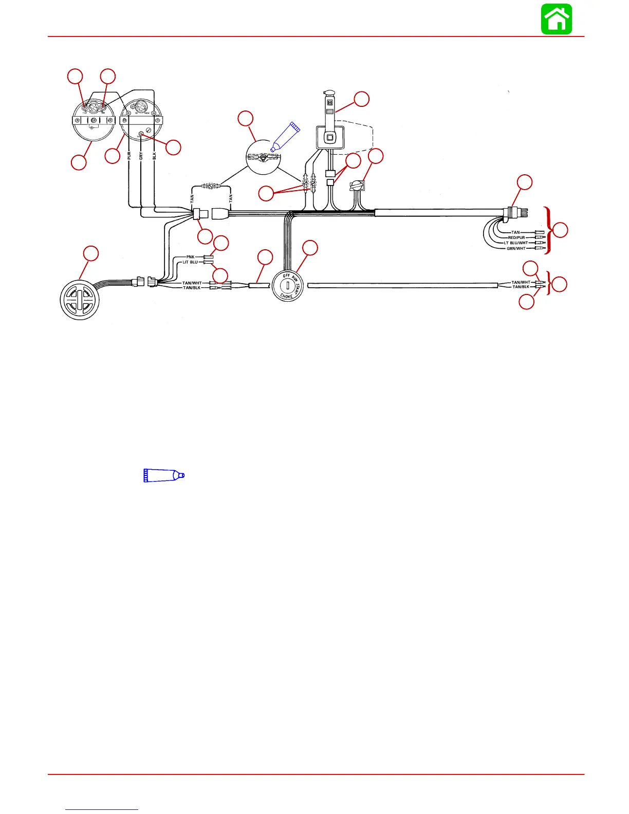
Panel Mount Remote Control Wiring Installation
BLK = Black
BLU = Blue
BRN = Brown
GRY = Gray
GRN = Green
ORN = Orange
PNK = Pink
PUR = Purple
RED = Red
TAN = Tan
WHT = White
YEL = Yellow
LIT = Light
DRK = Dark
ab
c
d
f
g
h
r
u
i
s
t
p
q
o
n
m
l
k
j
e
25
a
b
c
d
e
f
g
h
i
j
k
l
m
n
o
p
q
r
s
t
u
25
Liquid Neoprene (92-25711--2)
a-(+) 12 Volt Terminal
b-(–) Ground Terminal
c-Speedometer
d-Tachometer
e-Tachometer Signal Terminal
f-Connect Wires Together with
Screw and Hex Nut (3
Places); Apply Quicksilver Liq-
uid Neoprene to Connections
and Slide Rubber Sleeve Over
Each Connection.
g-Power Trim Connector
h-Horn
i-8 Pin Harness Connector
j-Multi-Function Gauge
k-Multi-Function Adapter Har-
ness
l-To Fuel Sender (Optional)
m-To Oil Sender (Optional)
n-Two Wire Harness
o-Ignition/Choke Switch
p-Low Oil Sender Lead
q-Over Temperature Switch
Lead
r-Panel Mount Remote Control
s-To Engine
t-To Engine
u-Neutral Safety Switch Lead

 Loading...


