POWER TRIM
90-855347R1 JANUARY 1999 Page 5B-21
Installation
1. Paint any exposed metal surfaces to prevent corrosion.
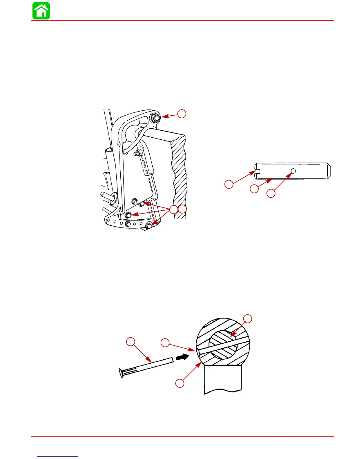
2. Apply Loctite 271 to screws. Install trim system, starboard transom bracket, and tilt
tube nut.
3. Use a 12 volt power source to extend tilt ram up to align upper swivel shaft hole and
end of ram. Connect trim motor wires [BLUE wire to POSITIVE (+), BLACK wire to
NEGATIVE (–)]. If ram extends too far, retract ram by connecting GREEN wire to POS-
ITIVE (+).
4. Install Upper Swivel Pin with slotted end to left (port) side of engine.
d
e
f
51375
a
b
c
a-Screw (6) Torque to 40 lb. ft. (54.0 N·m)
b-Lockwasher (6) Install one per screw
c-Tilt Tube Nut
d-Upper Swivel Pin
e-Slotted end
f-Cross hole (in line with slotted end)
IMPORTANT: Cross pin should not be reused. Install a new pin.
5. Position slot on end of swivel shaft in line with hole in tilt ram end. Insert a punch into
tilt ram hole to align cross hole in upper swivel shaft. Tap new cross pin in until flush.
a
d
b
c
a-Upper Swivel Shaft (Slot is in line with cross hole)
b-Chamfered End of Hole (Faces away from transom)
c-Retaining Pin
d-Tilt Ram End

 Loading...


