POWERHEAD
90-855347R1 JANUARY 1999 Page 4A-17
REMOVING ENGINE COMPONENTS
Remove the following engine components:
Section 2 Starter Motor
Starter Motor
*Electronic Control Module
*Ignition Coil
*Starter Solenoid
Alternator
Flywheel
Section 3
Direct Fuel Injection
Fuel Pump
On-Board Oil Tank
Oil Pump
Section 7
Shift Cable Latch Assembly
Control Cable Anchor Bracket
*All ignition and electrical components should remain attached to electrical plate.
Plate with components can be removed as an assembly.
Powerhead Disassembly
1. Place powerhead in repair stand or on a bench.
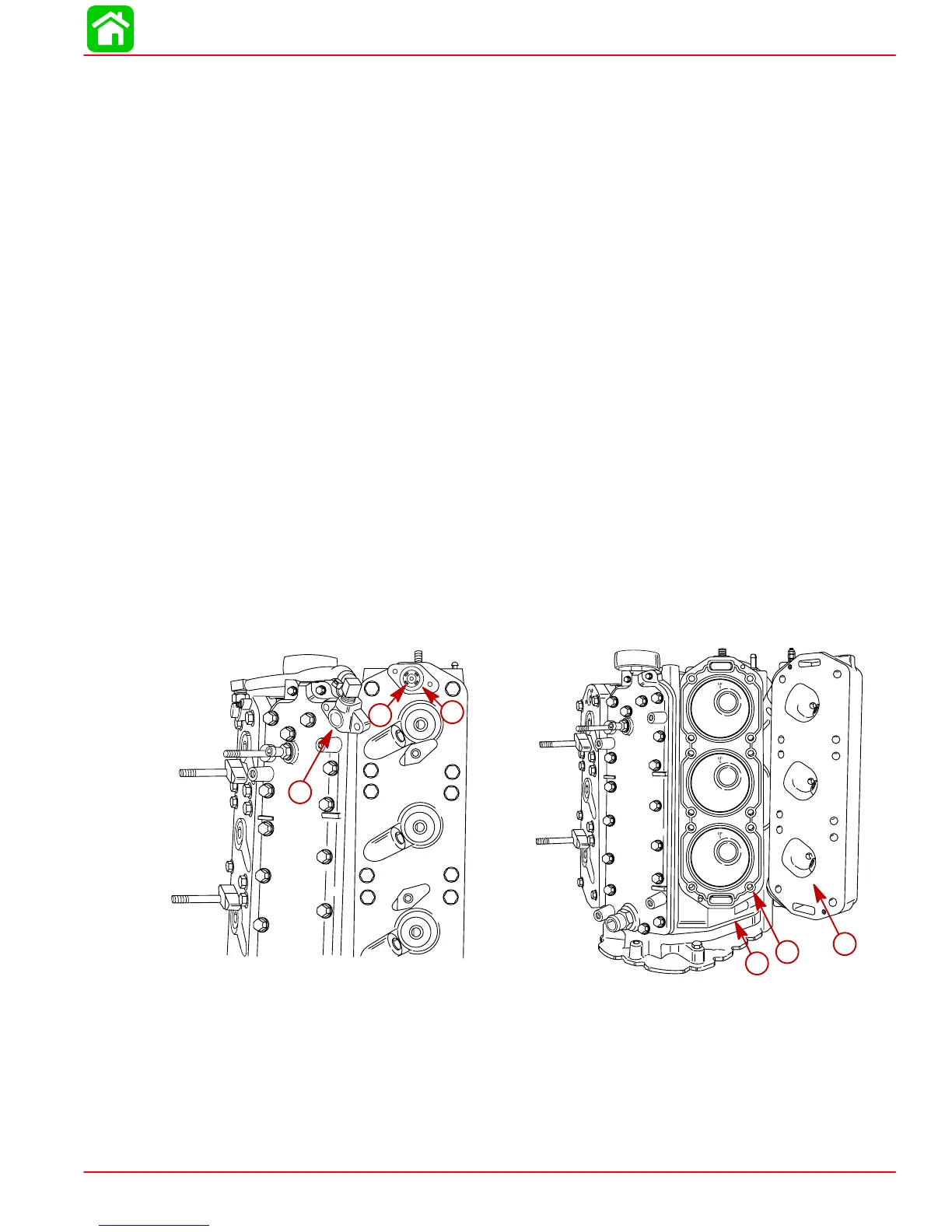
2. Remove thermostat covers, thermostats and gaskets.
3. Remove cylinder heads from engine block.
56165
d
e
f
56163
a
b
c
a-Thermostat Cover
b-Thermostat
c-Gasket
d-Cylinder Head
e-Gasket
f-Engine Block

 Loading...


