WIRING DIAGRAMS
90-855347R1 JANUARY 1999 Page 2D-9
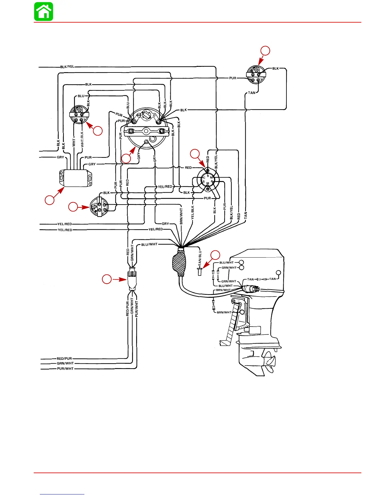
IMPORTANT: On installations where gauge options will not be used, tape back and
isolate unused wiring harness leads.
52206
i
g
a
e
j
f
m
o
STARBOARD INSTALLATION
BATT
GND
SENDER
g
i
j
f
m
o
a
e
i-Synchronizer Gauge
j-Synchronizer Module
k-Lanyard Switch (Isolation) Diode
l-Y Harness
m-Power Trim Harness Connector
n-Connect Wires together with Screw and Nut (4 Places); Apply Liquid Neo-
prene to Connections and slide Rubber Sleeve over each Connection.
o-Lead to Visual Warning Kit

 Loading...


