POWER TRIM
90-855347R1 JANUARY 1999 Page 5B-25
CAUTION
Failure to install spare tilt pin (or hardened bolts and nuts) in hole shown could
result in transom bracket failure and possible injury.
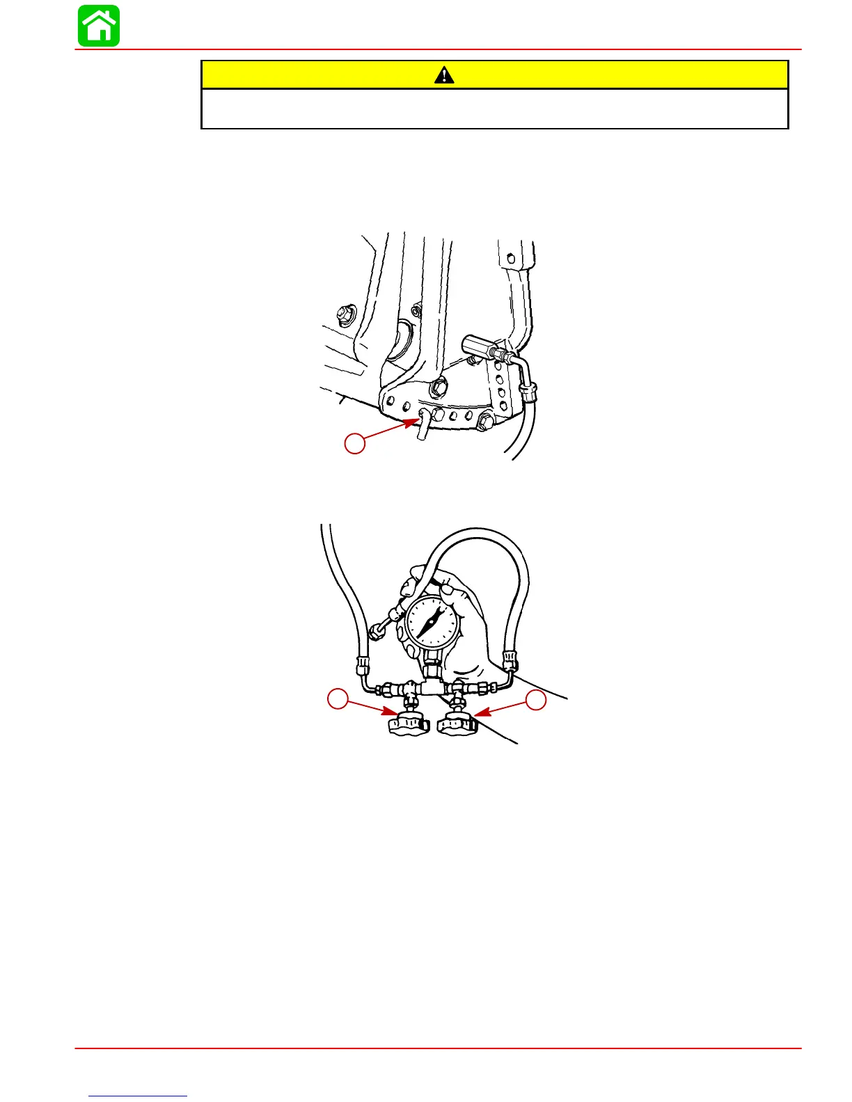
8. Move outboard “IN” until hole in swivel bracket “ear” aligns with the 3rd tilt hole in tran-
som bracket. Lock engine in trim range by installing a 3/8 in. (9.5 mm) diameter tilt pin
or two 3/8 in. (9.5 mm) hardened bolts and nuts thru the transom brackets and swivel
bracket in the hole shown.
a
54460
a-Tilt Pin Hole (Install Spare Tilt Pin or Hardened Bolts and Nuts)
9. Open valve (a) and close valve (b).
a
b
51374
10. Run trim “UP”. The minimum pressure should be 1300 P.S.I. (91 kg/cm
2
).
11. Run trim “DOWN” to release pressure and remove spare tilt pin or bolts and nuts.
12. Tilt outboard full “UP” and engage tilt lock lever.
13. Slowly remove “Fill” plug to bleed pressure.
14. Remove test gauge hose and adapter.
15. Reinstall Manual Release Valve and secure valve with circlip.
16. Retighten “Fill” plug.
NOTE: If pressure is less than 1300 PSI (91 kg/cm
2
), troubleshoot system per instructions
on page 5B-16.

 Loading...


