13.2 Mounting A Tool
The tool is held by the spacing collars.
A rough height positioning on the
spindle is done by placing spacing
collars under the tool as required.
Place tool on spindle (mind direction
of rotation) and spacing collars on top
right up to the spindle thread. Then
screw on the spindle nut.
For mounting or removing a tool it is
recommended to remove the fence
from the table.
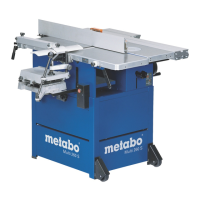
An auxiliary (or false) fence bridges
the gap between the two fence plates
to provide firm support and guiding for
small workpieces. Retracting the
fence, with the tool running, cuts
through the auxiliary fence.
Strips shorter than 200 mm must be held in user-made feeding jigs for
moulding.
1
2
3
9
8
7
6
5
4
10
11
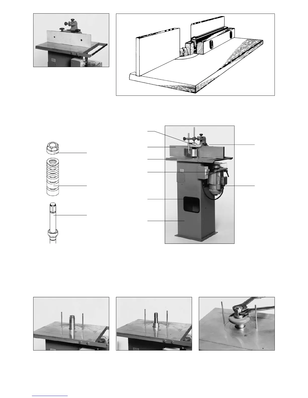
13 Controls
13.1 Definitions
1 Spindle
2 Spacing collars
3 Spindle nut
4 Main frame
5 Handwheel for spindle vertical adjustment
6 Starting switch
7 Table
8 Fence plates
9 Pressure shoe
10 Fence
11 Spindle lock

 Loading...