6 BC 71 en 7
Loosen the fastening screw (29) of the bearing unit
and the fastening screws of the cylinder (31) from
the cylinder base (6). Should the piston turn with the
screw (29), remove the end of the cylinder (44) and
stop the turning with the piston fastening screw (28).
See Figure 8.
Remove the cylinder and the piston, including the
rod.
Remove the old seals and the O-ring (24, 18, 19).
Remove the O-ring (16) and the bearing (22). Clean
the seal space.
Lubricate the seal space and the new O-ring with
Unisilikon L250L or equal silicone grease. Install the
new bearing and O-ring. See Figure 9.
Clean the piston seal groove and lubricate with a
thin layer of Cortec VCI 369.
Place the O-ring (18) under the piston seals.
Locate the seals (24) around the piston so that the
ends of the strips come on opposite sides. Tighten
the strips with the tie ring as shown in Figure 10. The
strips marked with an asterisk (*) may be cut 1.5-
3 mm shorter to facilitate assembly.
Knock or press the piston through the tie ring with a
press, Fig. 11.
Mount the O-ring (19) and the cylinder and piston.
Note the location of the air inlet: use the air inlet of
the cylinder base as a guide. Tighten the screws (31).
See Table 1 for torques.
Apply locking sealant e.g. Loctite 225 to the threads
of the fastening screw (29) of the bearing unit and
tighten it. See Table 1 for torque.
Fasten the housing cover temporarily so that the link-
age bearings (3) function, but the linkage is still visible,
Fig. 12. Note the grounding rings (3A, 4A).
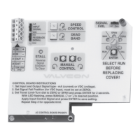
Fig. 8 Opening the fastening screw of the actuator bear-
ing unit
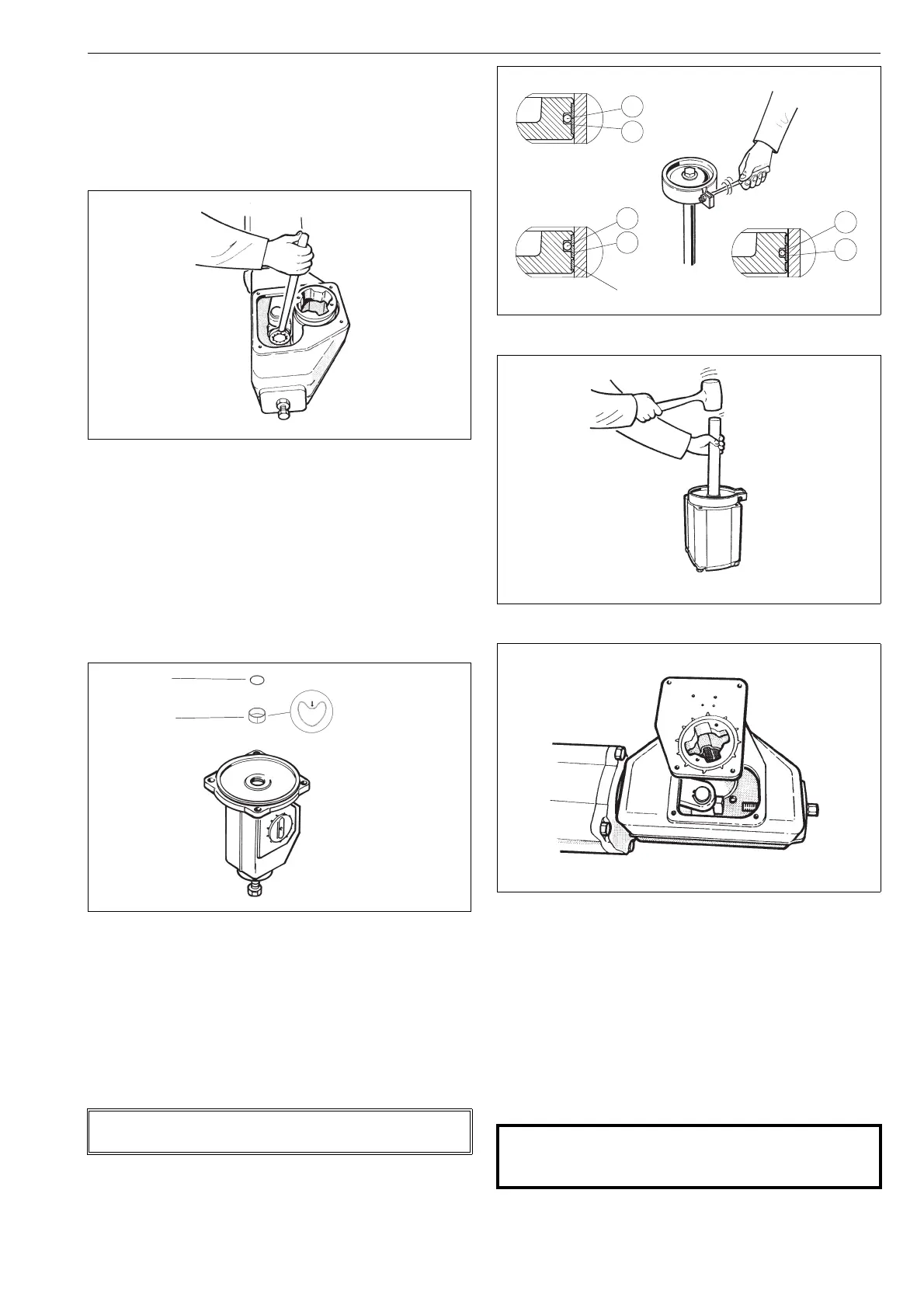
Fig. 9 Mounting the piston rod bearing and seal
NOTE:
The inside surface of the cylinder must be free of any grease!
Press the bearing
strip like this to
facilitate installation
16
22
Fig. 10 Tightening piston seals with a tie ring
Fig. 11 Placing the piston in the cylinder
Fig. 12 Mounting the cover on the housing
CAUTION:
Keep your fingers, tools or other items out of the hous-
ing while operating the actuator with the cover open!
 Loading...