6 BC 71 en 9
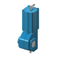
4.4 Maintenance of a B1CM actuator
The structure of the B1CM actuator is the same, except for
the manual operation lever connected with lever arm (3).
See the exploded view, Section 8.
Maintenance as in Sections 4.1 and 4.2.
4.5 Maintenance of B1C502-752 actuators
The structure of the B1C502-752 actuators is in principle the
same as a normal B1C actuator. In order to ensure a high
operating torque, the equipment is fitted with two cylin-
ders connected to the secondary shaft.
For maintenance see Sections 4.1 and 4.2.
5 MALFUNCTIONS
Table 2 lists malfunctions that might occur after prolonged
use.
6 TOOLS
For maintenance of the actuator, you will need a few special
tools in addition to the usual ones. The following can be
ordered from the manufacturer:
For actuator removal:
- Extractor (Table 3)
For piston seal installation:
- Tie ring (Table 4)
For cylinder base removal:
- Lock nut key (Table 5)
Table 3 Extractor tools
Table 4 Mounting Collars
Table 5 Shaft nut tools
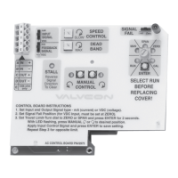
CAUTION:
Don’t use the lever in the torsion arm for manual oper-
ation when the actuator is pressurized!
CAUTION:
Don’t leave the lever in the torsion arm after manual
operation!
Actuator size Tool ID.
BC/BJ 6 303821
BC 8-11 / BJ 8-10 8546-1
BC 12-17 / BJ 12-16 8546-2
BC/BJ 20 8546-3
BC/BJ 25 8546-4
BC/BJ 32 8546-5
BC 40 / BJ 322 8546-6
BC 50 8546-7
BC 502 8546-8
Actuator size Tool ID.
BC 6-8 7814-1
BC 9-10 7814-2
BC 11-12 / BJ 8 7814-3
BC 13-16 / BJ 10 7814-4
BC 17-20 / BJ 12 7814-5
BC 25 / BJ 16 7814-6
BC 32 / BJ 20 7814-7
BC 40 / BJ 25 7814-8
BC 50, 502 / BJ 32, 322 7814-9
BC 60, 602 cylinder Ø 600 7814-10
BC 75, 752 7814-11
Actuator size Tool ID.
BC/BJ 8 260155
BC 10-11 / BJ 10 260156
BC 12-13 / BJ 12 260157
BC 16-17 / BJ 16 260172
BC/BJ 20 260196
BC/BJ 25 260195
BC 32 / BJ 32, 322 261153
BC 40 261154
BC 50, 502 261155
 Loading...