8 6 BC 71 en
Check the assembly of the cylinder to the cylinder
base and end. Connect the supply air to the cylinder
temporarely via a shut-off valve.
Operate the actuator and check the function of the
cylinder. Also check that the linkage bearings func-
tion properly. Remove the air supply and release
pressure from the cylinder.
Lubricate the linkage throughout with Cortec VCI
369 or an equivalent anti-corrosive agent to prevent
it from jamming due to rust.
Spread the sealant (e.g. silicone sealant) on the sur-
faces between the housing and the cover. Fasten the
cover, Fig. 12. See Table 1 for torques.
Mount the actuator to the valve and adjust the limits.
If you wish to remove the cylinder base, you will need a spe-
cial tool to open the lock nut (35), see Section 6. The nut
must be secured with e.g. Loctite 225 or equal liquid glue
when remounted.
4.3 Replacement of linkage bearings and
O-rings
Remove the actuator from the valve
Guide the actuator so that the piston is at the outer-
most end of the cylinder. Release the pressure from
the cylinder.
Remove the housing cover (2).
Loosen the fastening screw (29) of the bearing unit
(5), see Figure 8.
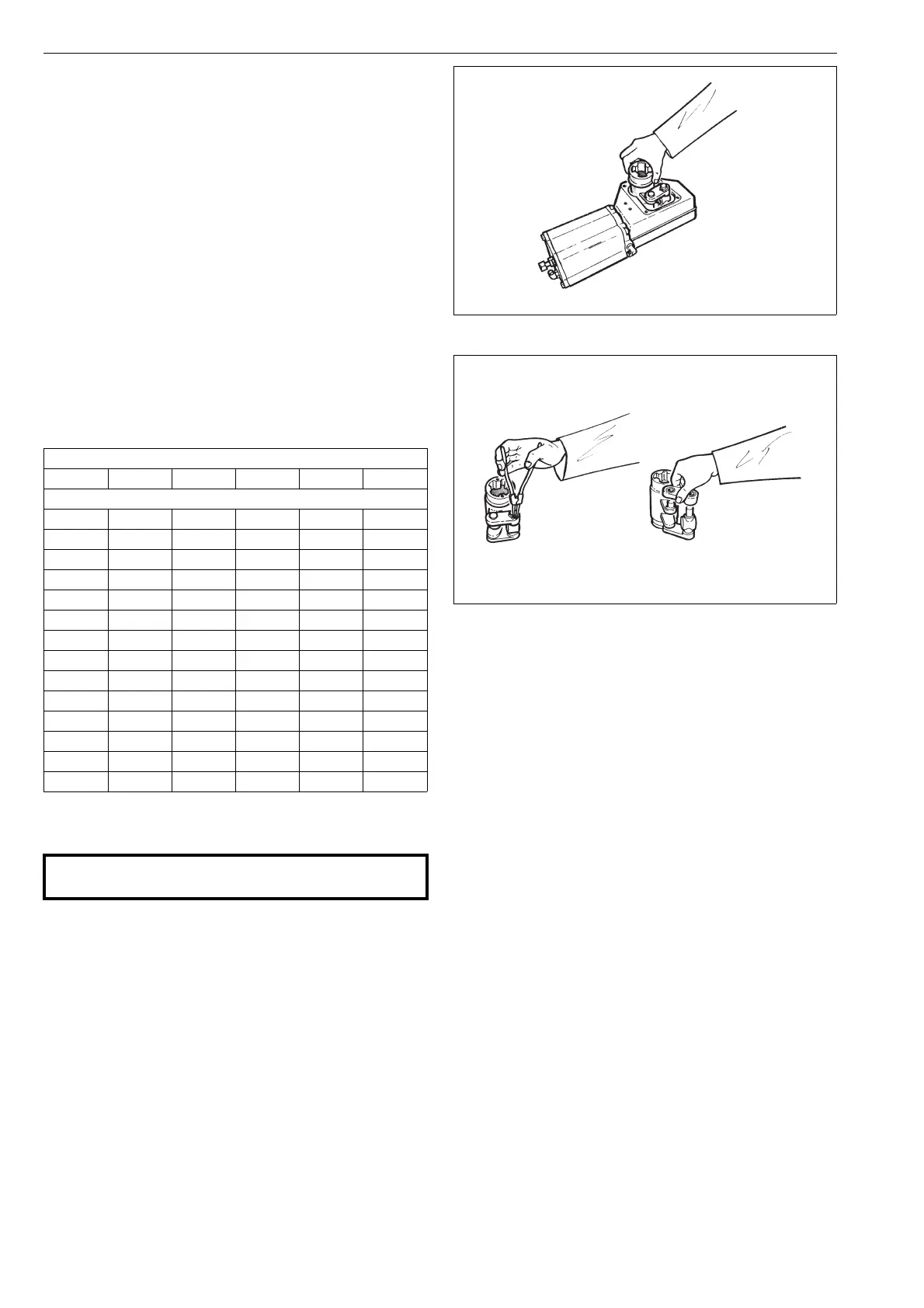
Turn the lever (3) so that the bearing unit is detached
from the piston rod (10). Lift the entire lever system
out of the housing, Figure 13.
Remove the lock rings (36) and the support rings
(37).
Loosen the connection arms (4) and ring (4A), clean
them and check the condition of the bearings, see
Figure 14.
The bearings (20, 21) of the connection arm (4) of B1C6-25
actuators are fastened with a press-on fit so that the entire
connection arm assembly is replaced instead of the bear-
ings. The bearings in actuators B1C32-75 are removable.
Remove the lever bearings (23), the O-rings (17) and
the grounding ring (3A).
Clean the parts of the levers and lubricate the bear-
ing and seal surfaces with Cortec VCI 369.
Install the grounding ring (3A), the lever bearings
(23) and the O-rings (17). The grounding rings (3A
and 4A) are needed to meet the ATEX requirements.
Assemble the linkage and install in the housing. See
Figure 13 for the correct position. Note the ring (4A).
Apply locking sealant e.g. Loctite 225 to the threads
of the fastening screw (29) of the bearing unit and
tighten it. See Table 1 for torque.
Lubricate the levers throughout with Cortec VCI 369
anti-corrosive.
Spread the sealant (e.g. silicone sealant) on the sur-
faces between the housing and the cover. Fasten the
cover, Fig. 12. See Table 1 for torques.
Operate the actuator and check that it moves cor-
rectly.
Cortec VCI 369 must be applied at six-month intervals in
damp conditions where corrosion is likely. Grease filling the
housing should also be considered. See Section 4.1.
Table 2 Tightening torques for screws
Torque, Nm
Item 28 29 30 31 35
Actuator
B1C 63535127
B1C 9 90 35 8 12 150
B1C 11 170 90 8 18 180
B1C 12 170 170 12 18 200
B1C 13 300 170 12 40 200
B1C 16 300 300 12 40 250
B1C 17 700 300 12 80 250
B1C 20 700 700 20 80 400
B1C 25 1100 1100 30 80 800
B1C 32 2000 2000 70 80 1500
B1C 40 2000 2000 70 200 2000
B1C 50 3400 3400 150 250 3000
B1C 60 3400 3400 150 250 3000
B1C 75 3400 3400 150 250 3000
CAUTION:
Don’t dismantle a pressurized actuator!
Fig. 13 Removing the linkage from the housing
Fig. 14 Dismantling the linkage
 Loading...