Troubleshooting
Index:
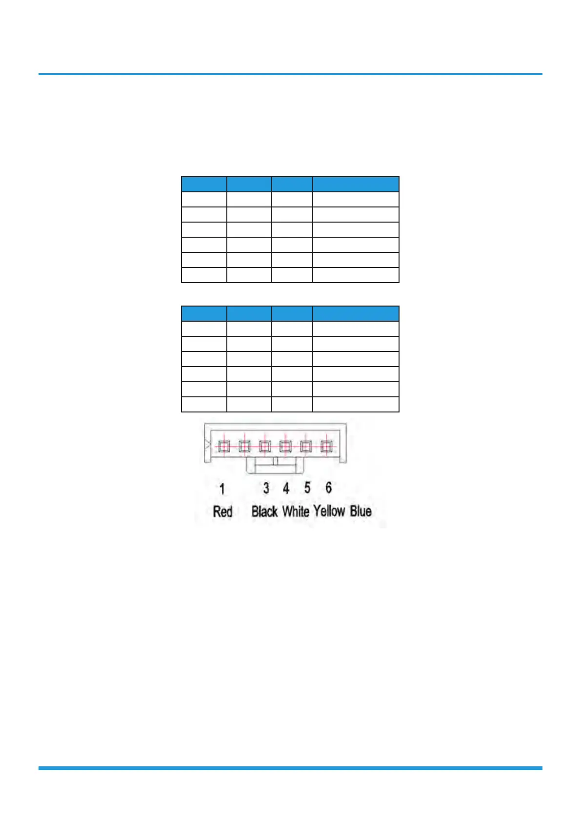
1. DC Fan Motor(control chip is in fan motor)
Power on and when the unit is in standby, measure the voltage of pin1-pin3, pin4-pin3 in fan motor connector. If the
value of the voltage is not in the range showing in below table, the PCB must has problems and need to be replaced.
• DC motor voltage input and output (voltage: 220-240V~):
No. Color Signal Voltage
1 Red Vs/Vm 192V~380V
2 --- --- ---
3 Black GND 0V
4 White Vcc 13.5-16.5V
5 Yellow Vsp 0~6.5V
6 Blue FG 13.5-16.5V
• DC motor voltage input and output (voltage: 115V~):
No. Color Signal Voltage
1 Red Vs/Vm 140V~190V
2 --- --- ---
3 Black GND 0V
4 White Vcc 13.5-16.5V
5 Yellow Vsp 0~6.5V
6 Blue FG 13.5-16.5V
 Loading...