V6R VRF 50/60Hz
171
Part 3 - System Design and Installation
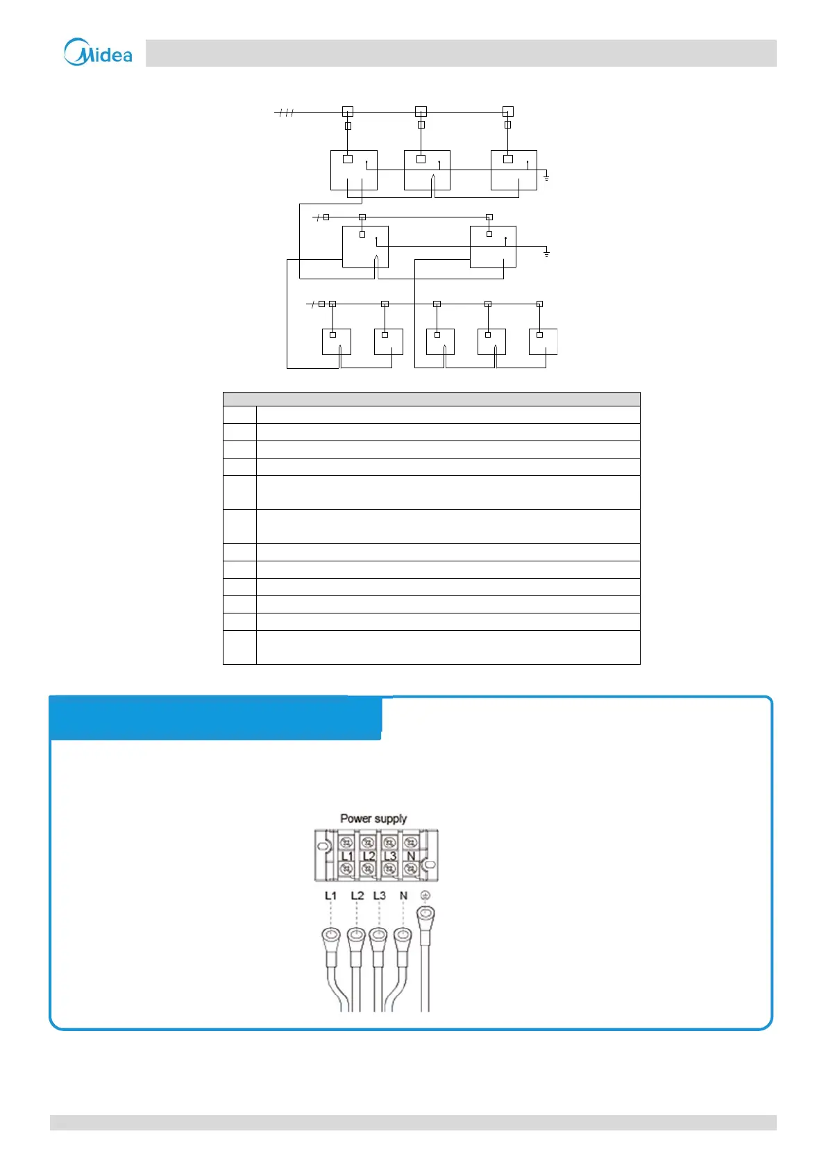
Figure 3-9.1: Overview of V6R system wiring
Legend
a Three‐phase power supply (with earth wiring and leakage protection)
b Power distribution box
c Power supply terminal of outdoor unit
d Single phase power supply (with earth wiring and leakage protection)
e
H1, H2 and E communication wire (with shielded layer) between outdoor
unit and outdoor unit
f
P,Q and E communication wire(with shielded layer) between outdoor unit
and MS box
g Earth wiring
h Outdoor unit
i VRF indoor unit
j Main switch (with leakage protection)
k MS box
m
P, Q and E communication wire (with shielded layer) between MS box and
Indoor unit
b bbbb
b b b
j
d
j
j
j
a
c
c
c
g
e
f
h
h
iiiii
d
j
b
b
h
kk
g
mm
The 3‐phase, 380‐415V, 50 or 60Hz of power supply should be connected to the outdoor unit power supply terminals
as shown in Figure 3‐9.2.
Figure 3-9.2: Outdoor unit 3-phase power supply terminals
Notes for installers
 Loading...