V6R VRF 50/60Hz
172
Midea V6R Series Engineering Data Book
9.3 Communication Wiring
Communication wiring design and installation should adhere to the following requirements:
Three‐core shielded cable should be used for communication wiring. The cross‐sectional area of each core of the
communication wiring is not less than 0.75 mm2, and the length must not exceed 1200 m. Using other types of cable
can lead to interference and malfunction.
Indoor communication wiring:
The P Q E communication wires should be connected one unit after another in a daisy chain from the outdoor unit
to the final indoor unit as shown in Figure 3‐9.4 and Figure 3‐9.5. At the final indoor unit (or HT hydro module), a
120Ω resistor should be connected between the P and Q terminals. After the final indoor unit (or HT hydro module),
the communication wiring should NOT be continued back to the outdoor unit – that is, do not attempt to form a
closed loop.
The shielding nets of the communication wires should be connected together and grounded. Grounding can be
achieved by connecting to the metal casing adjacent to the P Q E terminals of the outdoor unit electrical control
box.
Outdoor communication wiring:
The H1 H2 E communication wires should be connected one unit after another in a daisy chain from the master
outdoor unit to the last slave outdoor unit.
MS communication wiring:
MS box communication wires should be connected to the position with the label “P, Q, E ” and correspond to
the “P, Q, E ” wiring position for the outdoor and indoor units.
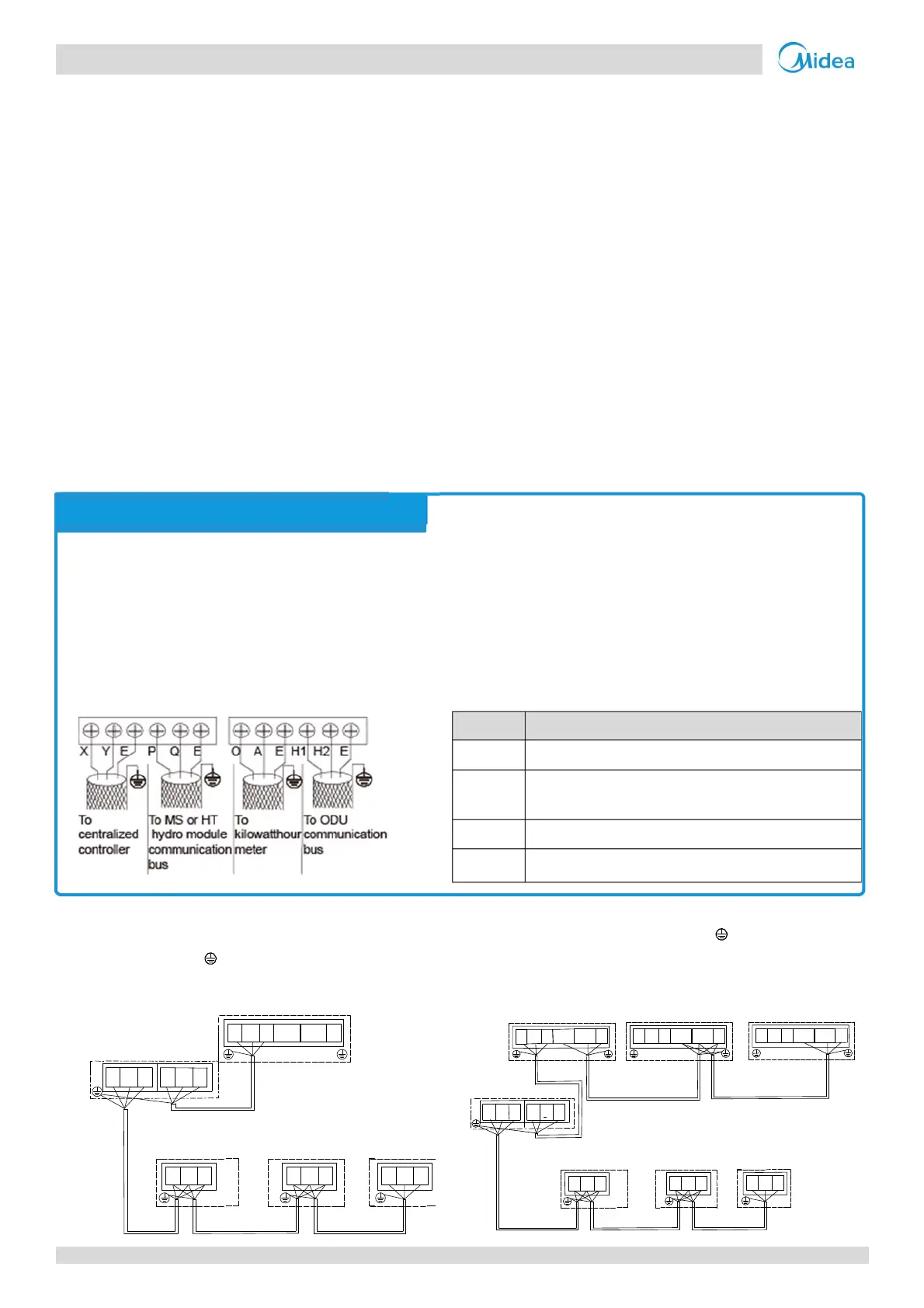
Figure 3-9.4: Communication wiring of single outdoor unit
Figure 3-9.5: Communication wiring of multi outdoor unit
IDU IDU IDU
P Q
P Q
P
Q
ODU
H1 H2P Q
MS
P
Q
P
Q
EE
E
E
E
E
E
O
D
U
(
M
a
s
t
e
r
)
O
D
U
(
S
l
a
v
e
)
O
D
U
(
S
l
a
v
e
)
I
D
UI
D
U
I
D
U
P
Q
P
Q
P
Q
H
1
H
2
P
Q
H
1
H
2
P
Q
H
1
H
2
P
Q
M
S
P
Q
P
Q
E
E
E
E
E
E
E
E
E
E
E
The communication wires should be connected to the master outdoor unit terminals indicated in Figure 3‐9.3 and Table
3‐9.1.
Caution
Communication wiring has polarity. Care should be taken to connect the poles correctly.
Figure 3-9.3: Master outdoor unit communication terminals Table 3-9.1: Communication connections
Terminals Connection
X Y E Connect to centralized controller
P Q E Connect between MS or high temperature hydro module
and master outdoor unit
O A E Connect to digital energy meter
H1 H2 E Connect between outdoor units
Notes for installers