EasyManua.ls Logo

Midea V6R Series User Manual

Midea V6R Series
131 pages
To Next Page IconTo Next Page
To Previous Page IconTo Previous Page
Page #81 background image
V6R VRF 50/60Hz
136
Midea
V6R
Series Engineering Data Book
4.3 Permitted Piping Lengths and Level Differences
4.3.1 Connection with only VRF indoor units
The piping length and level difference requirements that apply are summarized in Table 3-4.3 and are fully described as
follows (refer to Figure 3-4.2):
1. Requirement 1: The total length of piping in each refrigerant system should not exceed 1000m. When calculating the
total length of piping, the actual length of the indoor main pipes (the piping between the first indoor branch joint and
the MS box, L2 to L9) should be doubled.
2. Requirement 2: The piping between the farthest indoor unit and the first outdoor branch joint should not exceed 175m
(actual length) and 200m (equivalent length). (The equivalent length of each branch joint is 0.5m and the equivalent
length of each MS box is 1m.) When the equivalent piping length from outdoor units to the farthest indoor unit is larger
than 90 m, the liquid pipe of the main pipe (L1) should be increased as Table 3-4.2
3. Requirement 3: The piping between the farthest indoor unit (N8) and first indoor branch joint (A) should not exceed
40m in length (L2 + L4 + f + i 40m) unless the following conditions are met and the following measures are taken, in
which case the permitted length is up to 90m:
Conditions:
a) The piping from each indoor unit to its nearest branch joint or MS box does not exceed 40m in length (a to m each
≤ 40m).
b) The difference in length between {the piping from the first indoor branch joint (A) to the farthest indoor unit (N8)}
and {the piping from the first indoor branch joint (A) to the nearest indoor unit (N3)} does not exceed 40m. That
is: (L1 + L2 + L4 + f + i) - (L1 + L2 + L3 + c) 40m.
Measures:
a) Increase the diameter of the indoor main pipes (the piping between
the first indoor branch joint and the MS box, L
2
to L
9
) as per Table 3-
4.2, except for indoor main pipes which are already the same size as
the main pipe (L
1
), for which no diameter increases are required.
4. Requirement 4: The largest level difference between indoor unit and
outdoor unit should not exceed 110m.
If the outdoor unit is above and the level difference is greater than 50 m, the liquid pipe of the main pipe (L1) should
be increased as Table 3-4.2. And it is recommended that an oil return bend with
dimensions as specified in Figure 3-4.1 is set every 10m in the gas pipe of the
main pipe.
If the outdoor unit is below and the level difference is more than 40 m, the
liquid pipe of the main pipe (L1) should be increased as Table 3-4.2.
5. Requirement 5: The largest level difference between indoor units should not
exceed 30m.
6. Requirement 6: Piping between outdoor unit and outdoor branch joint should
not exceed 30m. g1 10 m; g2+G1 10 m; g3 + G1 10 m
Notes:
1. The size of main liquid pipe (L1) and indoor main liquid pipes (L2 to L9) can only be increased once if one or more of requirements are met in the requirement
2 to requirement 4.
Table 3-4.2: Diameter increase requirements
Original (mm)
Increased (mm)
Φ9.53
Φ12.7
Φ12.7
Φ15.9
Φ15.9
Φ19.1
Φ19.1
Φ22.2
Φ22.2
Φ25.4
Figure 3-4.1: Oil return bend (unit: mm)
300
or more
300
or more

Other manuals for Midea V6R Series

Question and Answer IconNeed help?

Do you have a question about the Midea V6R Series and is the answer not in the manual?

Midea V6R Series Specifications

General IconGeneral
BrandMidea
ModelV6R Series
CategoryAir Conditioner
LanguageEnglish

Summary

Part 1 General Information

1 Indoor and Outdoor Unit Capacities

Details capacities of indoor and outdoor units, including fresh air processing and heat recovery ventilators.

2 External Appearance

Illustrates the physical appearance of VRF indoor units, fresh air processing units, and heat recovery ventilators.

2.5 Mode Selection Box

Describes the MS box used for mode selection and its specifications.

3 Outdoor Unit Combinations

Describes various configurations and combinations of outdoor units.

4 Nomenclature

Explains the coding system used for identifying VRF indoor units and fresh air processing units.

5 Combination Ratio

Outlines the limitations and rules for combining indoor and outdoor unit capacities.

6 Selection Procedure

Provides a step-by-step guide for selecting VRF system components.

Part 2 Outdoor Unit Engineering Data

1 Specifications

Lists detailed technical specifications for various outdoor unit models.

2 Dimensions

Provides physical dimensions for single and combined outdoor units.

3 Center of Gravity

Shows the center of gravity for different outdoor unit configurations.

4 Installation Space Requirements

Details the necessary clearances for outdoor unit installation.

5 Piping Diagrams

Illustrates the refrigerant piping layouts for different outdoor unit capacities.

6 Wiring Diagrams

Presents wiring diagrams for outdoor units and mode selection boxes.

7 Electrical Characteristics

Details electrical data, including voltage, current, and power consumption.

8 Functional Components and Safety Devices

Describes the key functional parts and safety mechanisms of the outdoor units.

9 Capacity Tables

Provides detailed capacity data for heating and cooling operations.

10 Operating Limits

Outlines the operational temperature limits for cooling, DHW, and heating.

11 Sound Levels

Lists sound pressure levels and octave band data for outdoor units.

12 Accessories

Lists standard and optional accessories for outdoor units and mode selection boxes.

Part 3 System Design and Installation

1 Preface to Part 3

Introduces the content and purpose of Part 3, including notes for installers.

2 Unit Placement and Installation

Covers considerations for placing and installing outdoor and indoor units.

3 Outdoor Unit Ducting and Shielding

Details requirements and design considerations for outdoor unit ducting and shielding.

4 Refrigerant Piping Design

Covers design principles, material specifications, and permitted piping lengths.

5 Refrigerant Piping Installation

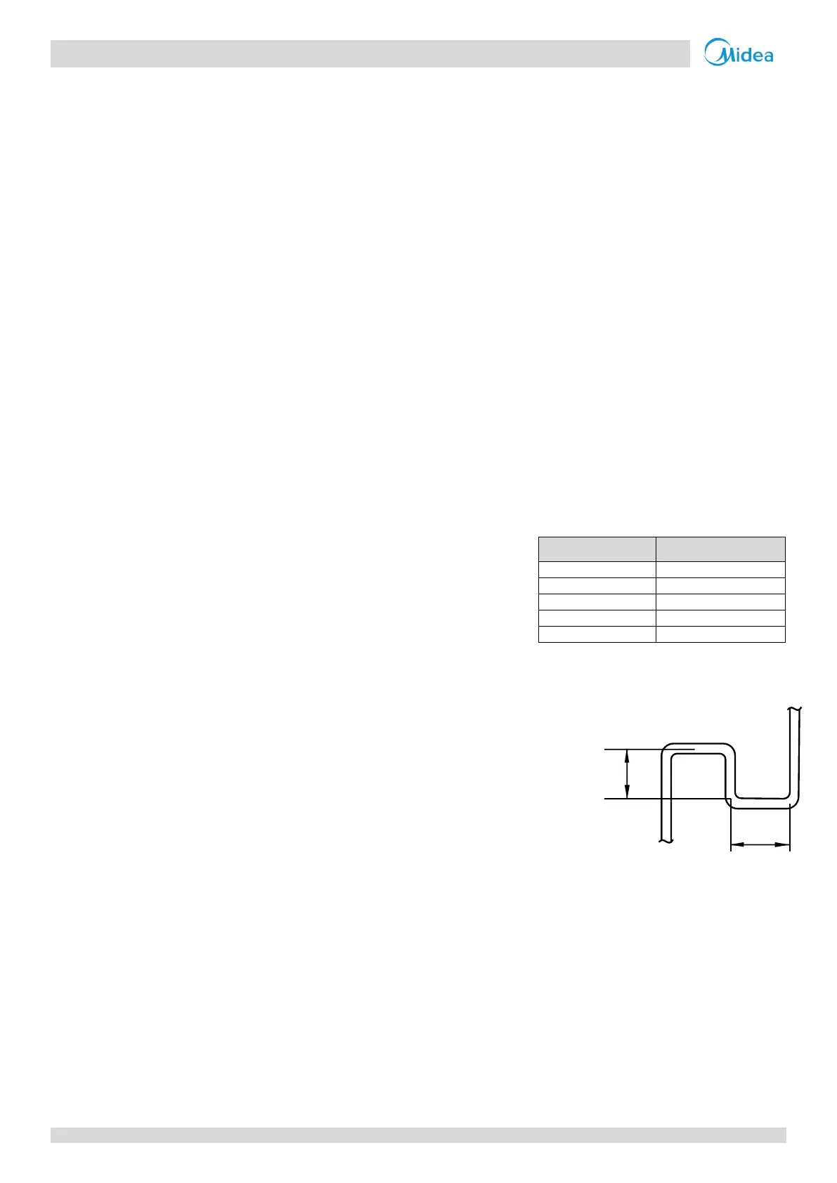
Provides procedures and principles for installing refrigerant piping, including brazing and flushing.

6 Drain Piping

Discusses design considerations, water traps, and selection of piping diameters for drain systems.

7 Insulation

Covers refrigerant piping insulation materials and thickness requirements.

8 Charging Refrigerant

Explains how to calculate and add refrigerant charge to the system.

9 Electrical Wiring

Details power supply, communication wiring, and wiring examples.

10 Installation in Areas of High Salinity

Provides specific guidelines for installing units in seaside environments.

11 Commissioning

Outlines procedures for unit configuration, pre-commissioning checks, and test runs.

12 Appendix to Part 3 – System Commissioning Report

Lists the report sheets required for system commissioning.

Related product manuals