19
GB
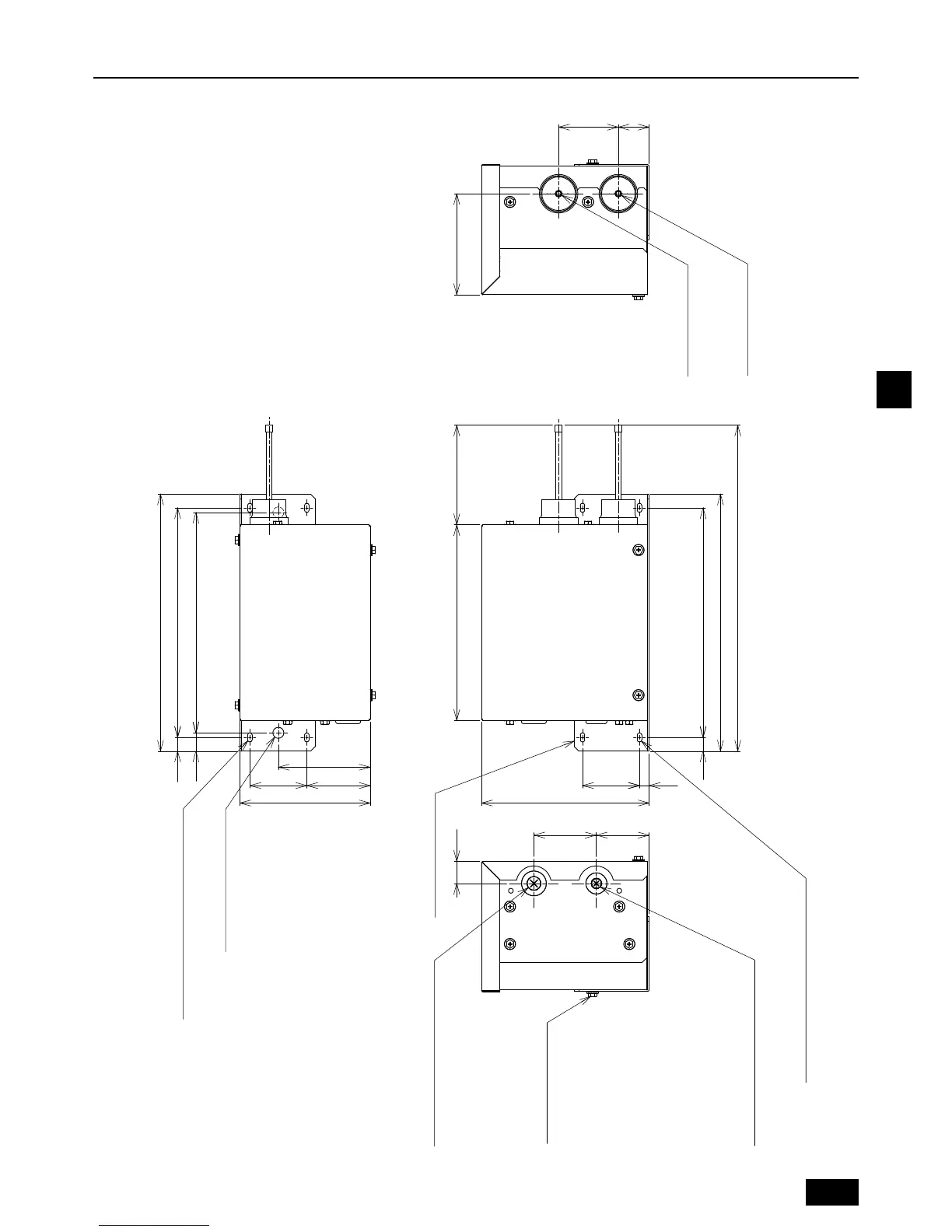
4. Outlines and dimensions
Note 3
Screw bolt (M5×10)
34
109
15
20
15
6858
24
Installation plate
2-ø12 holes
(For suspension bolt)
4-10×5 oblong holes
(For plane surface installation)
4-10×5 oblong holes
(For wall surface installation)
ޓ
㧨Accessories㧪
ޓInstallation plate
㨯㨯㨯㨯㨯㨯㨯㨯㨯㨯㨯㨯㨯㨯㨯㨯㨯㨯㨯㨯㨯㨯㨯㨯
1pc.
ޓGas thermistor
㨯㨯㨯㨯㨯㨯㨯㨯㨯㨯㨯㨯㨯㨯㨯㨯㨯㨯㨯㨯㨯㨯㨯㨯㨯㨯
1pc.
ޓThermistor holder (ø9.52)
㨯㨯㨯㨯㨯㨯㨯㨯㨯㨯㨯㨯
1pc.
ޓThermistor holder (ø12.7)
㨯㨯㨯㨯㨯㨯㨯㨯㨯㨯㨯㨯
1pc.
ޓScrew bolt (M5×10)
㨯㨯㨯㨯㨯㨯㨯㨯㨯㨯㨯㨯㨯㨯㨯㨯㨯㨯㨯㨯
2pc.
ޓPipe cover
㨯㨯㨯㨯㨯㨯㨯㨯㨯㨯㨯㨯㨯㨯㨯㨯㨯㨯㨯㨯㨯㨯㨯㨯㨯㨯㨯㨯㨯㨯㨯
2pc.
ޓCable band
㨯㨯㨯㨯㨯㨯㨯㨯㨯㨯㨯㨯㨯㨯㨯㨯㨯㨯㨯㨯㨯㨯㨯㨯㨯㨯㨯㨯㨯㨯
2pc.
100
240
㧨To outdoor unit㧪
Wiring to terminal block: TB5
㧨To gas pipe㧪
Wiring from gas thermistor
㧨POWER SUPPLY㧪
Wiring to terminal block: TB2
1-phase 220-240V 50, 60Hz
㧨To indoor unit㧪
Wiring to terminal block: TB
ø6.35㧨Brazed㧪
ø6.35㧨Brazed㧪
Connection pipe
of outdoor unit
Connection pipe
of indoor unit
280
250
213
142
69 62
65
110
355
280
250
183
11 62
Please attach a gas thermistor to the gas pipe of a spot.
When this is shipped from the factory, the installation
plate is not attached to the mainbody.
When you install the unit on a wall, please attach the
installation plate referring to the left figure. (M5×10)
When you use the suspension bolt, please attach the
installation plate inside out.
Suspension bolt (ø10), washer (M10), and nut (M10)
prepare in the field.
Note 1.
2.
3.
4.
5.
02_WT06728X03-body.fm 19 ページ 2013年12月25日 水曜日 午後1時29分

 Loading...