20
GB
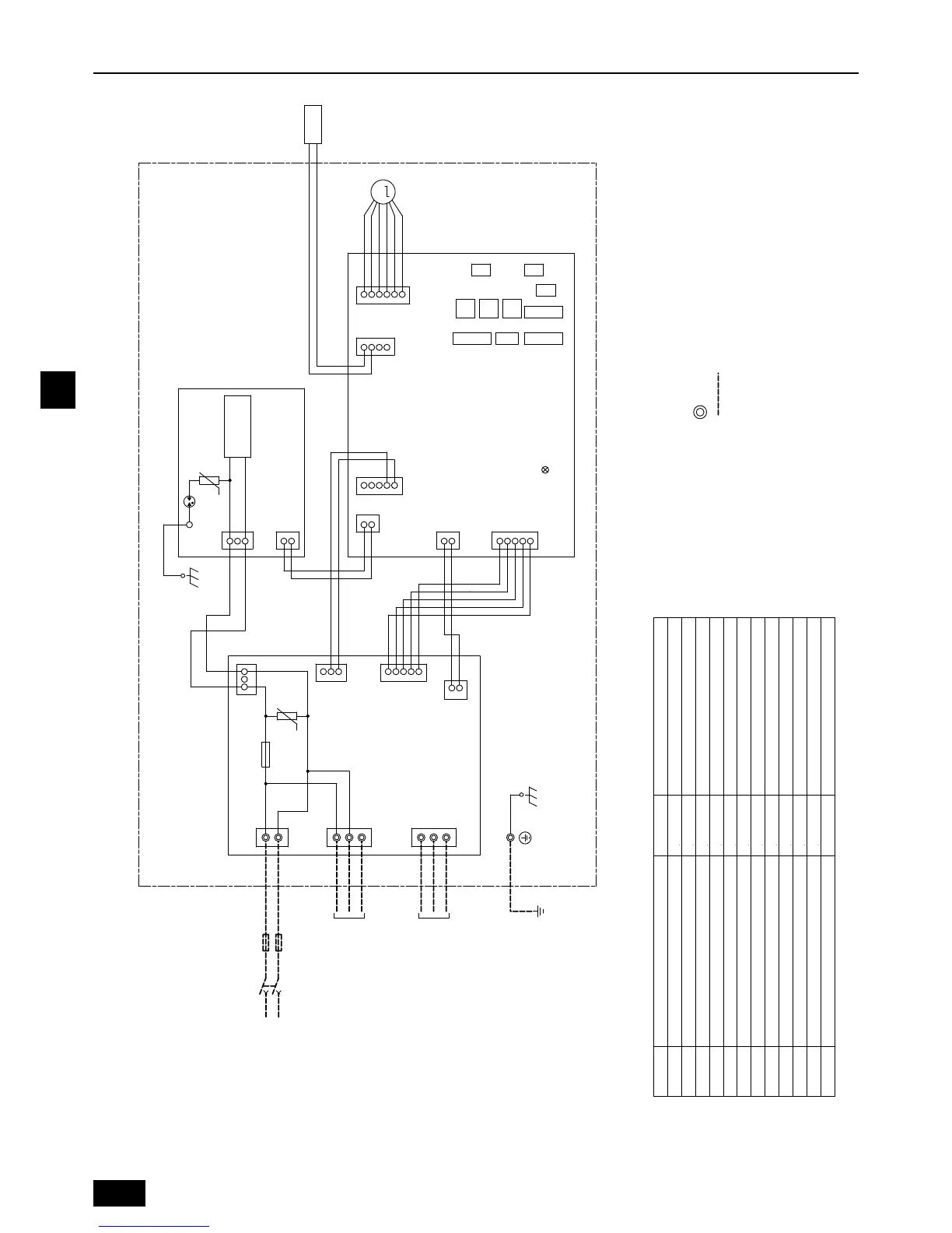
5. Wiring diagram
LED1
LED (Power supply)LED1
(Blue)
(Blue)
(Red)
(Red)
(Red)
M
DC280-340V
Rectifier circuit
LEV
ZNR001
NR
F001
A.B.
SW5
SWC
SW11
SW12
SW14
SWA
SW1 SW4
SW2
SW3
123
2
1
2
3
3
5
5
1
4
5
6
C.B.
P. B.
CITY MULTI CONNECTION KIT
3
2
2
4
4
4
2
2
2
2
2
2
3
4
5
1
1
3
3
3
1
1
1
1
1
1
1
2
CN60
CNXB2
CNXC2
CN2S
CNSK
SA
TAB1
CN351
CN570
CN450
CN001
TB2
TB
TB5
S1
L
M1
S2
N
M2
S3
S
CN44
TH23
CN2M
CN105
TO OUTDOOR UNIT
REMOTE CONTROLLER
U
U
POWER SUPPLY
ޓ AC220-240V
ޓ 50, 60Hz
TO INDOOR UNIT
BREAKER
FUSE
Thermistor (piping temp.detection/gas pipe)
Switch (for mode selection)
Switch (for capacity code)
Switch (10ths digit address set)
Switch (for static pressure selection)
Switch (for static pressure selection)
Switch (BRANCH No.)
Switch (for mode selection)
Switch (for model selection)
Switch (for mode selection)
Linear expansion valve
Fuse AC250V 6.3A
Varistor
Varistor
F001
NR
SA
ZNR001
LEV
TH23
SYMBOL
C.B.
P. B .
A.B.
Controller board
Power supply board
AT-adapter board
Surge Absorber
Switch (1s digit address set)
SW2(C.B.)
SW3(C.B.)
SW11(C.B.)
SW12(C.B.)
SWA(C.B.)
SW14(C.B.)
SWC(C.B.)
SW1(C.B.)
SW4(C.B.)
SW5(C.B.)
TB2
TB5
TB
Transmission terminal block
Transmission terminal block
Power source terminal block
SYMBOL EXPLANATION
NAME SYMBOL NAME
NOTE: Symbols used in wiring diagram above are,
:Terminal
(Heavy dotted line): Field wiring
02_WT06728X03-body.fm 20 ページ 2013年12月25日 水曜日 午後1時29分

 Loading...