-
44
-
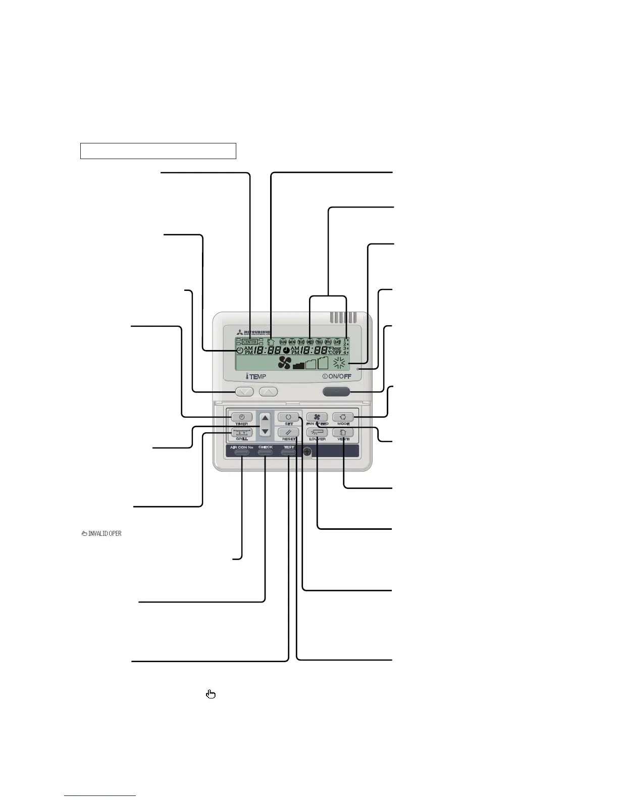
Weekly timer display
Displays the settings of
the weekly timer.
[Vent Indicator]
Indicates operation in the
Ventilation mode.
Operation/Stop switch
This switch is used to operate and
stop the air conditioning system.
Press the switch once to operate
the system and press it once again to
stop the system.
MODE switch
This switch is used to switch between
operation modes.
Operation setting display area
Displays setting temperature,
airflow volume, operation mode and
operation message.
Operation/Check indicator light
During operation: Lit in green
In case of error: Flashing in red
FAN SPEED switch
This switch is used to set the
airflow volume.
(AUTO, HI POWER or ECONO cannot be selected.)
SET switch
This switch is used to apply the timer
operation setting.
This switch is also used to reset the
“FILTER CLEANING” message display.
(Press this switch after cleaning the air filter.)
Central control display
Displayed when the air conditioning
system is controlled by the option controller.
Timer operation display
Displays the settings related to
timer operation.
AIR CON No. (Air conditioning system No.) switch
Displays the number of the connected
air conditioning system.
[CHECK switch]
This switch is used at servicing.
[TEST switch]
This switch is used during test operation.
Temperature setting switches
These switches are used to set
the temperature of the room.
[VENT switch]
Switch that operates the
connected ventilator.
Timer setting switches
These switches are used to set
the timer mode and time.
TIMER switch
This switch is used to select
a timer mode.
(The comfortable timer cannot be
selected.)
[GRILL switch]
This switch has no function.
When this switch is pressed,
(Invalid Operation)
is displayed, but it does not mean a failure.
LOUVER switch
This switch is used to operate/stop
the swing louver.
This button is not used for SRRM-ZF series.
(Air flow direction adjustment can not be performed.)
27
˚
C
* If you oress any of the switches above and “ INVALID OPER” is display, the switch has no function.
But it does not mean a failure.
(2) Wired remote control (Optional parts)......STM, SRRM only
The figure below shows the remote control with the cover opened. Note that all the items that may be displayed in the liquid crystal display
area are shown in the figure for the sake of explanation.
Characters displayed with dots in the liquid crystal display area are abbreviated.
Note (1) The STM, SRRM models don't support the switches and functions displayed in [ ].
Pull the cover downward to open it.
 Loading...