-
56
-
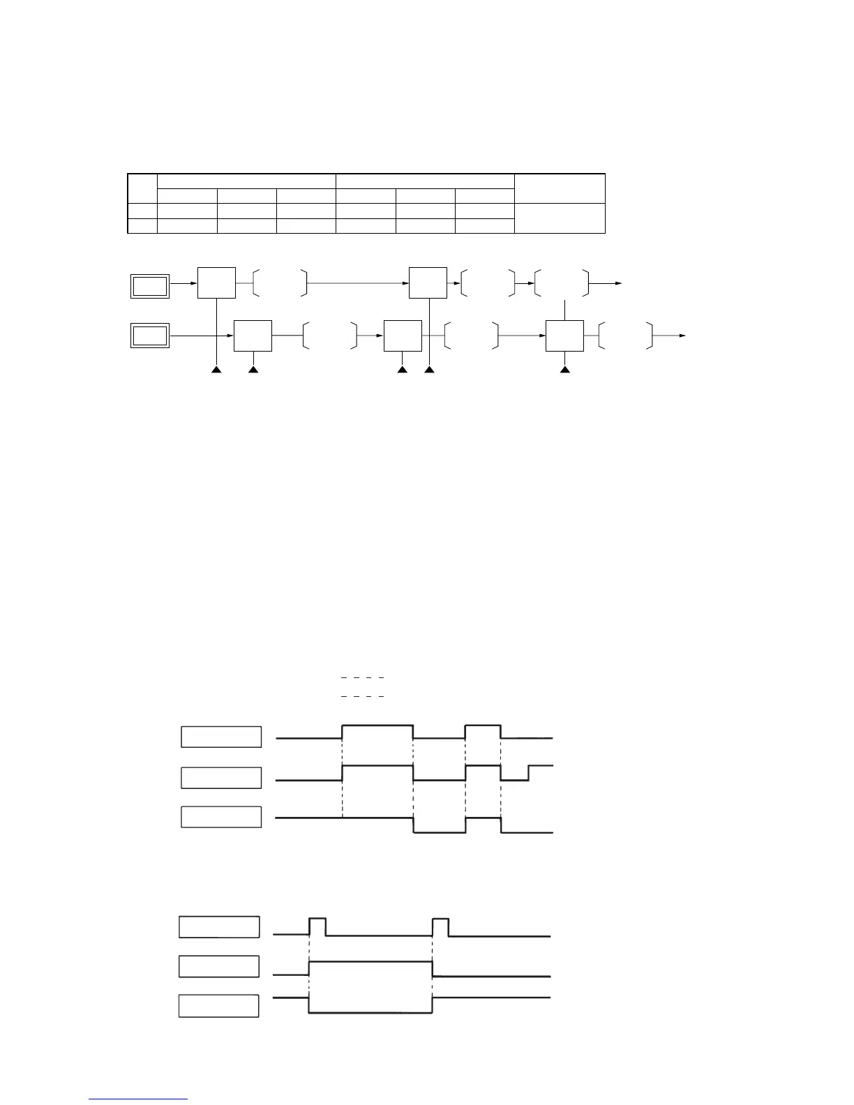
4.10 Determining the operating mode
The cooling and heating operating modes are the remote control switch mode that have been previously determined.
If a mode differing from these is selected after this, the selected mode will appear in the display of the remote control, but only the fan
will operate.
A unit
B unit
Cooling
Cooling
Fan Heating
HeatingFan
Cooling
switch
ON
Heating
switch
ON
Heating
switch
ON
Cooling
switch
ON
Heating
switch
ON
Operation Operation
Operation Operation
Operation
Example of operating pattern
Note (1) [ ] indicates currect operation.
First operation Second operation
Notes
Selected Mode
Cooling
Heating
Example
1
2
Remote Control Display
Cooling
Heating
Operation
Cooling
Heating
Selected Mode
Heating
Cooling
Remote Control Display
Heating
Cooling
• Different mode is
only fan operation.
Operation
Fan
(1)
Fan
Note (1) If the display shows heat-
ing and the operation is
fan, Hot Keep will oper-
ate.
(b) When Jumper wire J1 on the PCB of indoor unit is cut at the field or “PULSE INPUT” is selected in the wired remote
control’s indoor unit settings.
Input signal to CnT becomes valid at OFF → ON only and the motion of air conditioner [ON/OFF] is inverted.
CnT Input
A Unit
B Unit
OFF
OFF
*ON
ON
ON
ON
OFF
OFF
OFF
ON
ON
ON
OFF
OFF
OFF
Note (1) The ON with the * mark indicates
an ON operation using the remote
control unit switch, etc.
*ON
4.11 External control (remote display) /control of input signal (STM, SRRM only)
Make sure to connect the wired remote control unit. Control of input signal is not available without the wired remote control unit.
(1) External control (remote display) output
Following output connectors (CNT) are provided on the printed circuit board of indoor unit.
(a) Operation output: Power to engage DC 12V relay (provided by the customer) is outputted during operation.
(b) Heating output: Power to engage DC 12V relay (provided by the customer) is outputted during the heating operation.
(c) Compressor ON output: Power to engage DC 12V relay (provided by the customer) is outputted while the
compres sor is operating.
(d) Error output: When any error occurs, the power to engage DC 12V relay (provided by the customer) is outputted.
(2) Control of input signal
Control of input signal (switch input, timer input) connectors (CNT) are provided on the control circuit board of the indoor unit.
However, when the operation of air conditioner is under the Center Mode, the remote control by CnT is invalid.
(a) If the factory settings (Jumper wire J1 EXTERNAL INPUT on the PCB) are set, or “LEVEL INPUT” is selected in the wired
remote control’s indoor unit settings.
1) Input signal to CnT OFF → ON Air conditioner ON
2) Input signal to CnT ON → OFF Air conditioner OFF
CnT Input
A Unit
B Unit
OFF
OFF
ON
ON
OFF
ON
OFF
ON
ON
OFF
OFF
 Loading...