-
104
-
'19 • SCM-SM-276
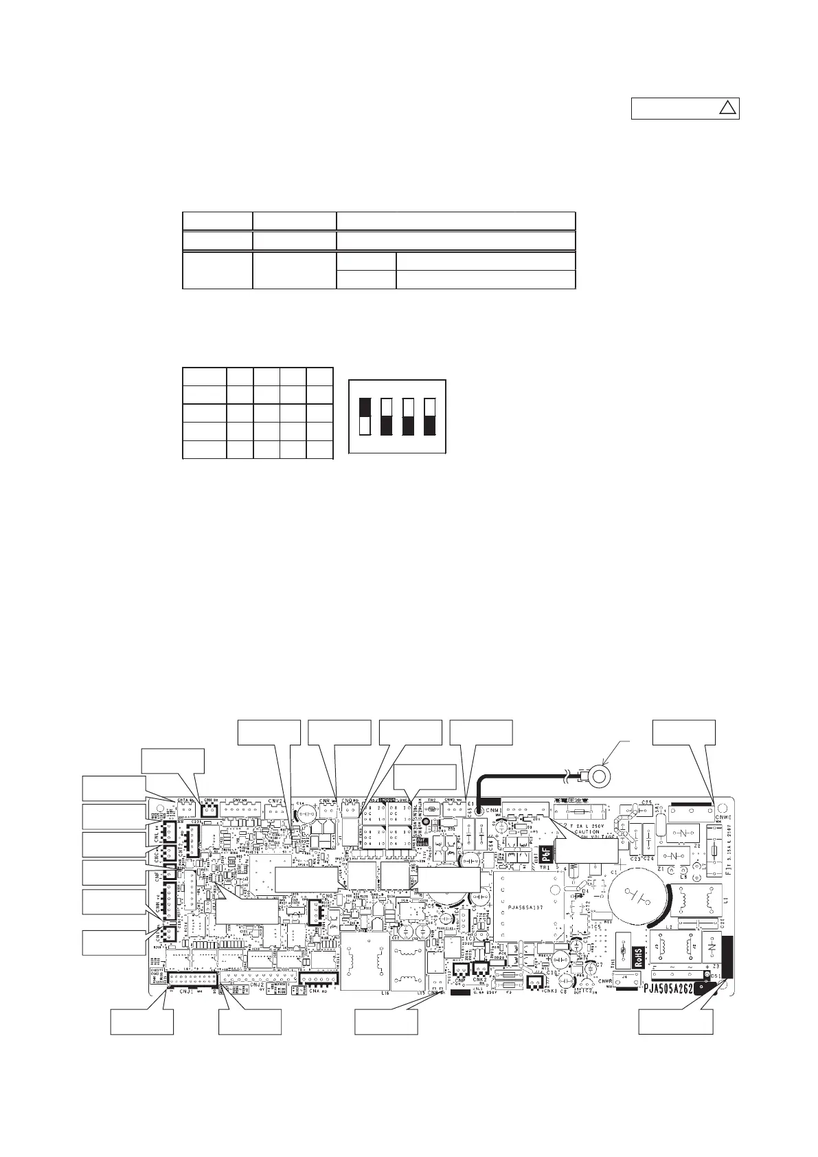
Replace and set up the PCB according to this instruction.
1) Set to an appropriate address and function using switch on PCB.
Select the same setting with the removed PCB.
2) Set to an appropriate capacity using the model selector switch(SW6).
Select the same capacity with the PCB removed from the unit.
Switch
SW2
OFF
ON
Content of control
Plural indoor units control by 1 remote control
Test run SW7-1
Normal
Operation check/drain motor test run
SW6
ON
1 2 3 4
Example setting for 25VH
SW6 -1 -2 -3 -4
25VH
ON
OFF
OFF
ON
OFF
50VH
OFF
ON OFF
ON OFF
35VH
OFF OFF
ON ON
60VH
ON OFF
3) Replace the PCB
a) Unscrew terminal (Arrow A) of the "E1" wiring (yellow/green) that is connected to PCB.
b) Replace the PCB only after all the wirings connected to the connector are removed.
c) Fix the board such that it will not pinch any of the wires.
d) Switch setting must be same setting as that of the removed PCB.
e) Reconnect the wirings to the PCB. Wiring connector color should match with the color of connector of the PCB.
f) Screw back the terminal (Arrow A) of the "E1" wiring, that was removed in a).
4) Control PCB
Parts mounting are different by the kind of PCB.
PSC012D050
C
①Replace the pwb
1. Unscrew terminal(Arrow A) of the "E1" wiring(yellow/green) that is connected to pwb.
2. Replace the pwb only after all the wirings connected to the connector are removed.
3. Fix the board such that it will not pinch any of the wires.
4. Switch setting must be same setting as that of the removed pwb.
5. Reconnect the wirings to the pwb. Wiring connector color should match with the color of connector of the pwb.
6. Screw back the terminal(Arrow A) of the "E1" wiring, that was removed in 1.
②Control pwb
Parts mounting are different by the kind of pwb.
CNW3 (White)SW5CNR (White)LED3 (Red)
CNH (Black)
CNTA (Blue)
CNL (Black)
CNC (White)
CNT (Blue)
CNN (Yellow)
CNI (Blue)
CNJ1 (White) CNJ2 (Grey) CNB (Black)
CNM1(White)
A
LED2 (Green)
CNW0 (White)
Part number
SW2
SW7
SW6
(i) FDTC series
 Loading...