Chapter 2 Specifications
2–14
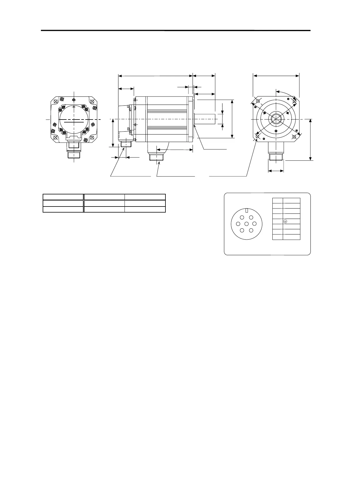
• HC353R(B)S
• HC503R(B)S
(Unit : mm)
46
□130
3
Oil seal
S30457B
21.5
Detector
connector
Power supply
connector
KL
44
L
63
58
12
Note 3
Note
3
81.5
4-
φ
9
Installation hole
Use a hexagon
socket head bolt.
φ
1
4
5
φ
1
6
5
120
4
5
°
φ
28h6
φ
110h7
Note
3
MS3102A22-14P
CE05-2A24-10P
Servomotor type L (Note 1) KL
HC353R(B)S 222 (258) 148
HC503R(B)S 279 (315) 205
Note 1. The dimensions given in parentheses are for when magnetic brakes
are provided.
Note 2. Use a friction coupling (Spun ring, etc.) to connect with the load.
Note 3. For the magnetic brakes.
Note 4. Refer to section 2-9 for details on the detector connector.
CE05-2A24-10P
B1
D
Signal
U
V
W
B
A
Pin
C
E
B2
F
G
A
B
C
F
E
D
G
Power supply connector
Grounding
B1 and B2 are the brake terminals.
(Only for motor with brakes.)
24VDC with no polarity.
 Loading...


