GENERAL INFORMATION
TSB Revision
INTAKE AND EXHAUST
15-2
GENERAL INFORMATION
M1151000101041
The exhaust pipe is divided into three parts.
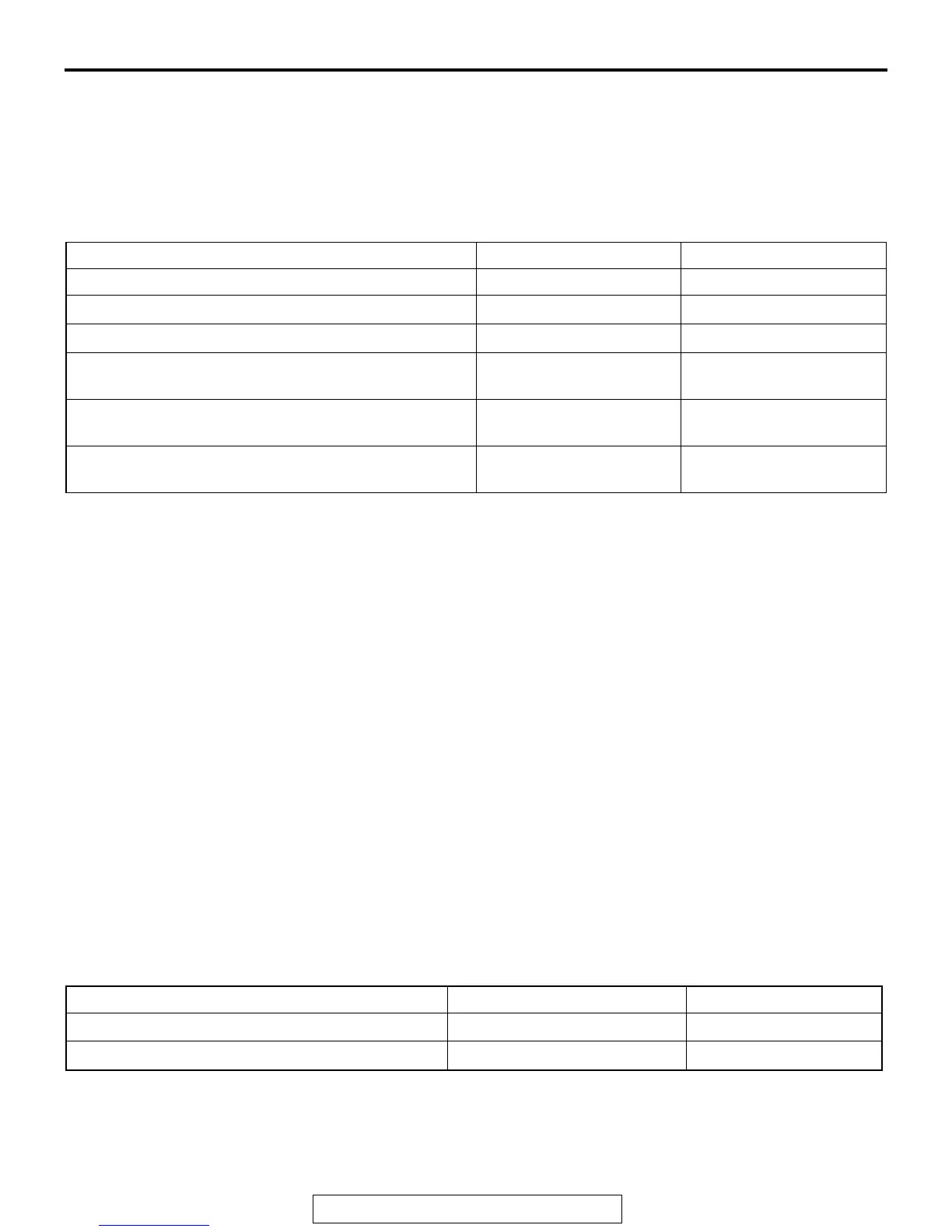
SERVICE SPECIFICATION
M1151000301335
ITEM STANDARD VALUE LIMIT
Manifold distortion of the installation surface mm (in) 0.15 (0.006) or less 0.20 (0.008)
Intake charge pressure kPa (psi) 85 − 159 (12.4 − 23.0)
−
Turbocharger waste gate actuator pressure kPa (psi) 98 − 102 (14.3 − 14.7)
−
No. 1 Turbocharger waste gate solenoid terminal
resistance [at 20
° C (68° F) ] Ω
29 − 35
−
No. 2 Turbocharger waste gate solenoid terminal
resistance [at 20
° C (68° F) ] Ω
29 − 35
−
Exhaust manifold distortion of the installation surface
mm (in)
−
0.70 (0.028)
INTAKE AND EXHAUST DIAGNOSIS
INTRODUCTION
M1151006900406
Intake leaks usually create driveability issues that
are not obviously related to the intake system.
Exhaust leaks or abnormal noise is caused by
cracks, gaskets and fittings, or by exhaust pipe or
muffler damage due to impacts during travel. The
exhaust leaks from these sections and causes the
exhaust noise to increase. There may be cases
when the system contacts the body and vibration
noise is generated.
TROUBLESHOOTING STRATEGY
M1151007000398
Use these steps to plan your diagnostic strategy. If
you follow them carefully, you will be sure that you
have exhausted most of the possible ways to find an
intake or exhaust system fault.
1. Gather information from the customer.
2. Verify that the condition described by the
customer exists.
3. Find the malfunction by following the Symptom
Chart.
4. Verify malfunction is eliminated.
SYMPTOM CHART
M1151007100395
Symptom Inspection procedure Reference page
Exhaust Leakage 1
P.15-3
Abnormal Noise 2
P.15-3
 Loading...