AC210667
Cooling fan motor
connector:
Harness side
MB991222
Circuit tester
Fan controller
AB
ON-VEHICLE SERVICE
ENGINE COOLING
14-17
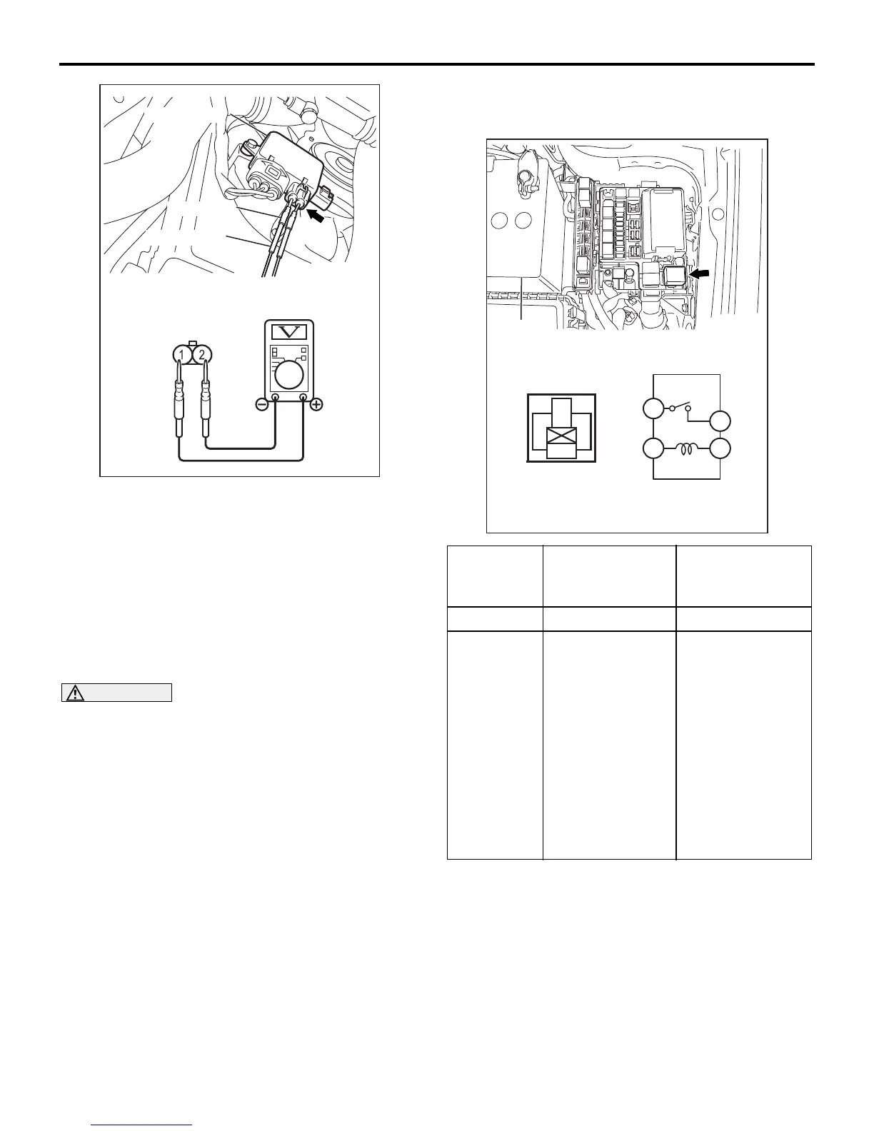
5. Insert special tool probe (MB991222) at the back
of the cooling fan motor connector.
6. Connect the special tool to the circuit tester.
7. Ensure that the A/C switch is off, and start the
engine and run it at idle.
8. Measure the voltage between the cooling fan
motor connector terminals.
Standard value: 1V or less
9. Turn the A/C switch to the "ON" position.
WARNING
Stay clear of the fan when the fan starts run-
ning.
10. Measure the voltage between the cooling fan
motor connector terminals while the fan is
running. The voltage should repeat the values 1)
and 2) below.
Standard value:
1) 8.2 ± 2.6 V
2) Battery positive voltage ± 2.6 V
11.If the voltage does not repeatedly change as
indicated, replace the fan controller.
12.Install the centre under cover (Refer to GROUP
51, Front Bumper
P.51-2).
FAN CONTROL RELAY CONTINUITY
CHECK
M1141006200354
13
4
2
3
4
1
2
AC210672
Battery
AB
Battery
voltage
Terminal No.to
be connected to
tester
Continuity test
results
Not applied 4 − 2 Open circuit
• Connect
terminal
No.1 and
battery
(+)
terminal.
• Connect
terminal
No.3 and
battery
(
−)
terminal.
4 − 2 Less than 2 ohms
COOLING FAN MOTOR CHECK
M1141007100134
1. Remove the centre under cover (Refer to GROUP
51, Front Bumper
P.51-2).
 Loading...