3 Controller
Names of each part 3-36
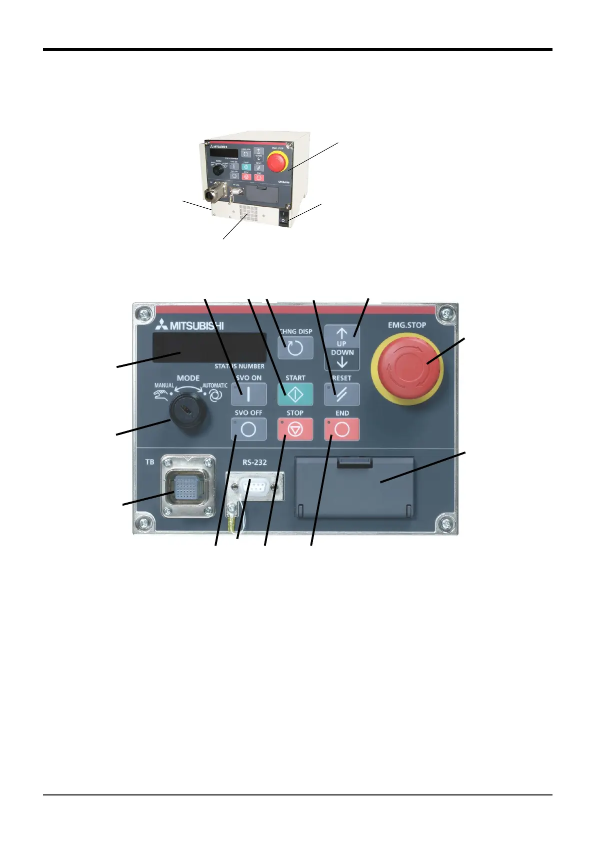
3.2 Names of each part
Fig.3-1 : Names of controller parts (CR1DA-700 series)
①
POWER switch
Note 1)
..................... This turns the control power ON/OFF. (With earth leakage breaker function)
② START button....................................This executes the program and operates the robot. The program is run continuously.
③ STOP button ......................................This stops the robot immediately. The servo does not turn OFF.
④ RESET button ....................................This resets the error. This also resets the program's halted state and resets the program.
⑤ Emergency stop switch..................This stops the robot in an emergency state. The servo turns OFF.
⑥ CHNGDISP button ...........................This changes the details displayed on the display panel in the order of "Override" → "Pro
-
gram No." → "Line No.".
⑦ END button..........................................This stops the program being executed at the last line or END statement.
⑧ SVO.ON button..................................This turns ON the servo power. (The servo turns ON.)
⑨ SVO.OFF button ............................. This turns OFF the servo power. (The servo turns OFF.)
⑩ STATUS NUMBER
(display panel).....................................The alarm No., program No., override value (%), etc., are displayed.
⑪ T/B connection connector .........This is a dedicated connector for connecting the T/B. When not using T/B, connect the
attached dummy connector.
<CR1DA-700 series>
< Operating panel >
②
④
⑤
⑥
⑧
⑬
⑫
⑩
⑨
⑭
⑦
③
⑪
⑮
①
< Operating panel >
⑯
(Right side)
⑰
* The figure is standard specification.
CE marking specification is the same.
 Loading...


