54
4.6 RS232C Interface (A1SCPUC24-R2 only)
(1) RS-232C connector specifications
A 9-pin D subconnector is supplied in the same package as the
A1SCPUC24-R2 body.
Product name
9-pin Dsub (male), screw mounted
17JE-23090-02-D8A, made by DDK
(2) RS-232C cable
For the RS-232C cable, use a cable that conforms to the
RS-232C standard and is no longer than 15 m.
(Recommended cable)
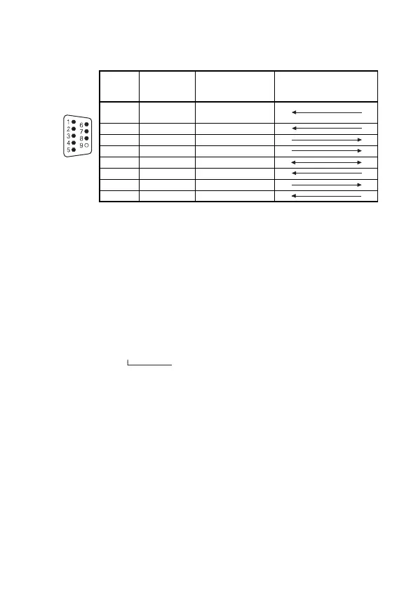
(3) Connecting the RS-232C connectors
The standard method for connecting the RS-232C connectors is
shown below.
For details on the connection method, refer to the Computer Link
Module User's Manual (Com. link func./Print func.).
Pin
Number
Signal
Abbreviation
Signal Name
Signal Direction
A1SCPUC24-R2
↔External Device
1CD
Receive carrier
detection
2 RD(RXD) Receive data
3 SD(TXD) Send data
4 DTR(ER) Data terminal ready
5 SG Signal ground
6 DSR(DR) Data set ready
7 RS(RTS) Request to send
8 CS(CTS) Clear to send
7/0. 127[ ]P HRV-SV..............(RS-232C cable made by Oki Densen)
Specify the number of wire pairs.
For example, if the number of pairs is thirteen:
7/0. 127 13P HRV-SV

 Loading...


