57
4.7 Self-Loopback Test (A1SCPUC24-R2 only)
The self-loopback test checks whether or not the isolated A1SCPUC24-
R2 (not connected to any external devices) will operate correctly.
For details on the self-loopback test, refer to the Computer Link Module
User's Manual (Com. link func./Printer func.).
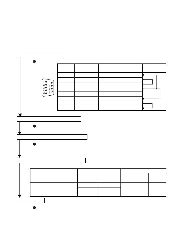
Connect cables to the RS-232C connectors.
Pin
Number
Signal
Abbreviation
Signal Name
Cable
Connections
1 CD Receive carrier detection
2 RD(RXD) Receive data
3 SD(TXD) Send data
4 DTR(ER) Data terminal ready
5 SG Signal ground
6 DSR(DR) Data set ready
7 RS(RTS) Request to send
8 CS(CTS) Clear to send
Set the mode setting switch to "F".
Turn the programmable controller CPU power supply ON or reset the
programmable controller CPU.
Check Item Display When Normal Display in Error Status
Programmable controller
CPU communications check
C/N OFF
C/N
(LED No.7)
ON
CPU Flicker
RS-232C communications
check
SIO OFF
SIO
(LED No.10)
ONSD
Flicker
RD
Turn the power supply OFF.
Connect the cables
Set the mode setting switch
Execute the self-loopback test
Check the LED display status
Completed

 Loading...


