39
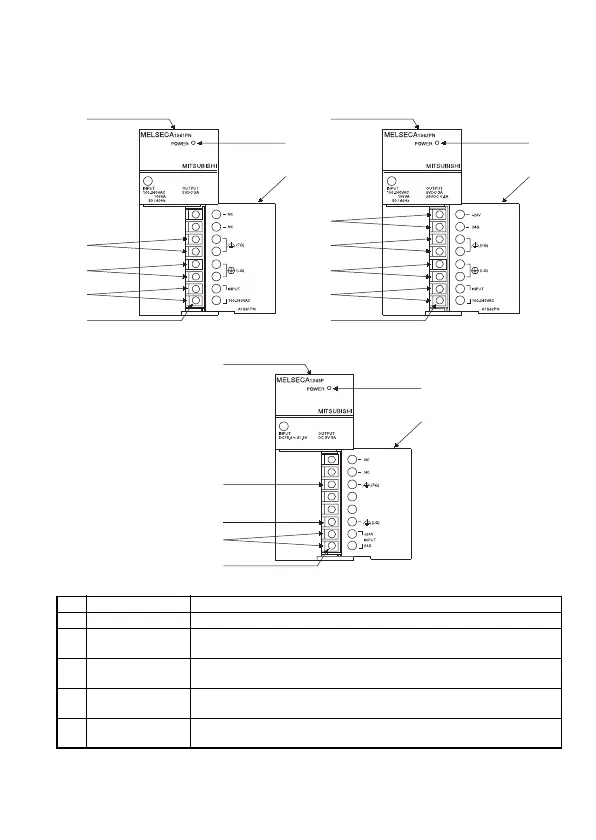
4.3.2 Parts names
The following gives the names and description of the parts of the power
supply modules :
No. Name Description
[1] POWER LED The indicator LED for the 5 V DC power.
[2]
24 V and 24 G
terminals
Used to supply 24 V DC to inside the output module
(using external wiring).
[3] FG terminal
The grounding terminal connected to the shield pattern of the printed
circuit board.
[4] LG terminal
Grounding for the power supply filter. The potential of A1S61PN or
A1S62PN terminal is 1/2 of the input voltage.
[5]
Power supply
input terminals
Used to connect a 24 V DC power supply.
(3) A1S63P
(2) A1S62PN(1) A1S61PN
[6]
[7]
[5]
[4]
[3]
[1]
[9]
[3]
[4]
[8]
[7]
[6]
[2]
[1]
[9]
[3]
[4]
[8]
[7]
[6]
[1]
[9]

 Loading...


