ABS <4WD> -
Troubleshooting
35B-22
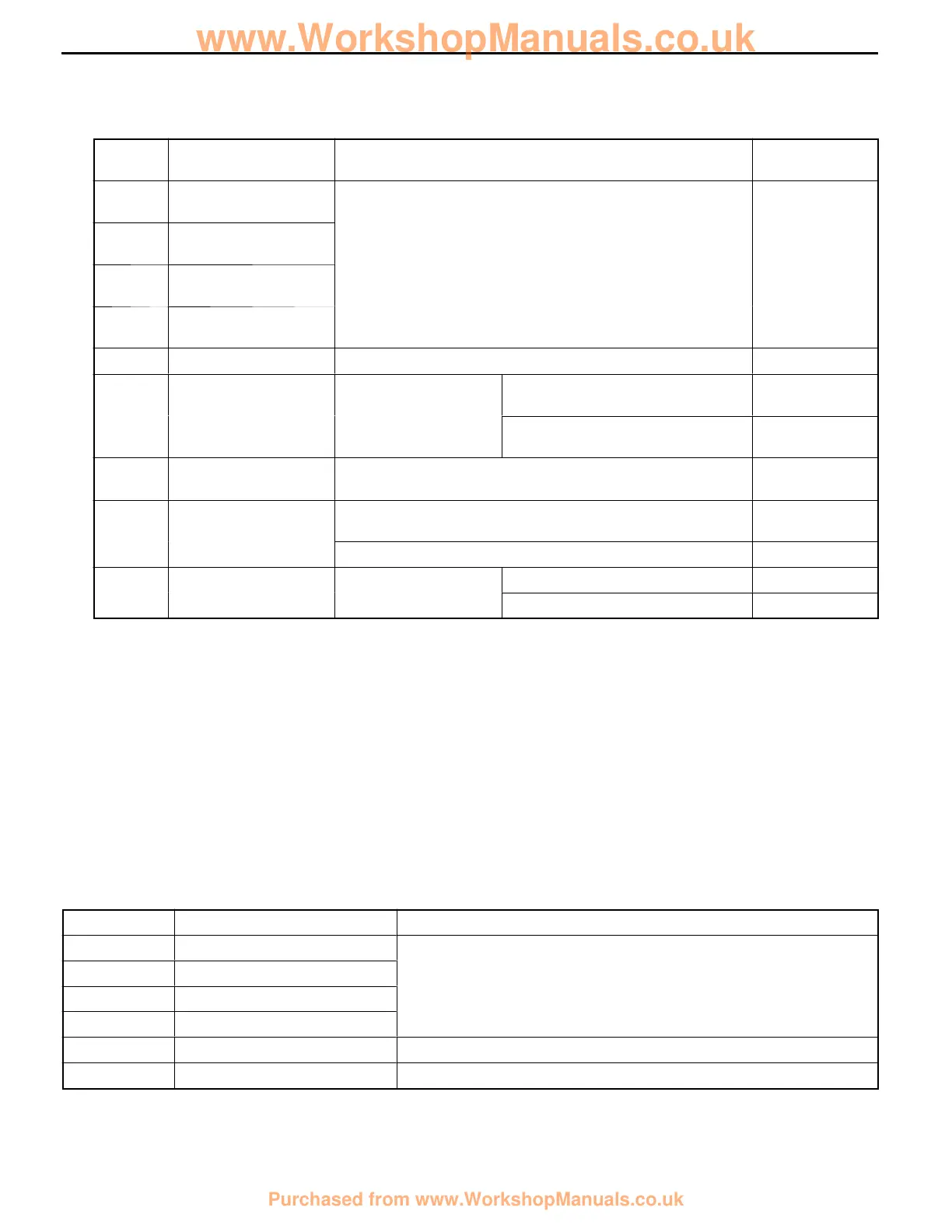
DATA LIST REFERENCE TABLE
The following ECU input data items can be read using the MUT-
II
.
(1) When system is normal
Item
No.
Check item Inspection conditions Normal condi-
tion
11 Front- right wheel
speed
When vehicle is being driven Speedometer
display and
12 Front- left wheel
speed
MUT-II display
are identical.
13 Rear- right wheel
speed
14 Rear- left wheel
speed
16 System voltage Ignition switch: ON 6.5- 22.3 V
26 Center differential
lock switch
Ignition switch: ON
Transfer selector lever position:
2H, 4H
OFF
Transfer selector lever position:
4HLc, 4LLc
ON
27 Rear differential lock
switch
Ignition switch: ON OFF
32 G sensor
D
Ignition switch: ON
D
When vehicle is stationary (level)
2.4- 2.6 V
When vehicle is being driven 1.0- 4.0 V
33 Stop lamp Ignition switch: ON
When brake pedal is depressed ON
Switch
When brake pedal is released OFF
(2) When system is interrupted by t he ECU
When the diagnosis function has caused the operation of the ABS-ECU to be stopped, the
MUT-
II
display data may be different from the actual condition.
ACTUATOR TEST TABLE
The following actuators can be force-driven using the MUT-
II
.
NOTE
(1) Actuator tests cannot be carried out when the operation of the ABS-ECU has been stopped by
the fail-safe function.
(2) Actuator tests can only be carried out while the vehicle is stopped.
ACTUATOR TEST SPECIFICATIONS
Item No. Check item Drive Contents
01 FR wheel solenoid valve
HBB select solenoid valves and control solenoid valves for the
02 FL wheel solenoid valve
respective channel
03 RR wheel solenoid valve
04 RL wheel solenoid valve
27 Air bleeding (1) HBB select solenoid valves and control solenoid valve OUT (FR, FL)
28 Air bleeding (2) HBB control solenoid valve OUT (RR, RL)
www.WorkshopManuals.co.uk
Purchased from www.WorkshopManuals.co.uk
 Loading...