ABS <4WD> -
On-vehicle Service
35B-27
ON-VEHICLE SERVICE
WHEEL SPEED SENSOR OUTPUT VOLTAGE
MEASUREMENT
NOTE
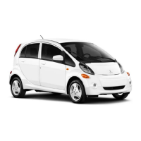
There are two ECUs with the same shape inside the
floor console, one above the other. The upper ECU is
the ABS-ECU and has a blue connector. The lower ECU
is the transfer-ECU and has a green connector.
(1) Lift up the vehicle and release the parking brake.
(2) Disconnect t he ABS-ECU connector a n d measure at t he
harness-side connector.
(3) Rotate the wheel to be measured by 1/ 2 to 1 turn , and
use a multimeter (AC mV range) or an oscilloscope to
check the output voltage at this time.
Terminal No.
Front- left Front- right Rear- left Rear- right
7 10 9 8
20 23 22 21
Output voltage:
42 mV or higher when measured using a
multimeter
120 mVP - P or more when measured using an
oscilloscope
(4) If the output voltage is lower than that given above, the
cause may be the following, so check or replace the
wheel speed sensor if necessary.
D
Excessive clearance between pole piece of wheel
speed sensor and ABS rotor
D
Malfunction of wheel speed sensor
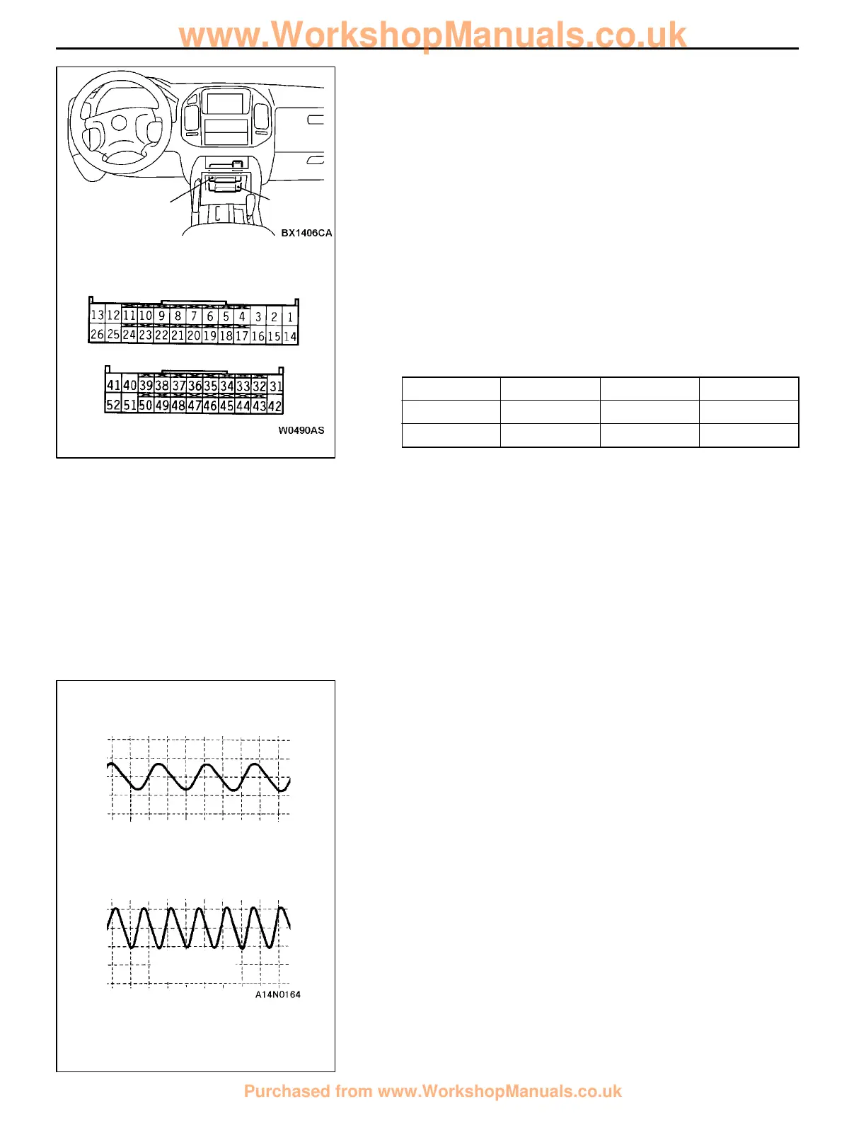
WAVE PATTERN INSPECTION USING AN
OSCILLOSCOPE
After checking the connection of the wheel speed sensor
harness and the connector, take a reading of the output voltage
wave patterns for each wheel speed sensor using an
oscilloscope as follows.
Start the engine, move the transfer selector lever to the 4H
position and the transmission selector lever to D range (A/T)
or 1st gear (M/T), and then spin the wheel.
NOTE
(1) You can also take a reading of the wave pattern by actually
driving the vehicle in this condition.
(2) The output voltage will be lower when the wheel speed
is lower, and will become higher as the wheel speed
becomes higher.
Harness-side connector
ABS-
ECU
Transfer-ECU
When rotated by
hand
When engine is idling (5 - 6
km/h)
D range (A/T) or 1st gear (M/T)
10.0 ms/DIV
IV/DIV
www.WorkshopManuals.co.uk
Purchased from www.WorkshopManuals.co.uk
 Loading...