36
DISASSEMBLY INSTRUCTIONS
11
OPERATING PROCEDURE
PHOTOS
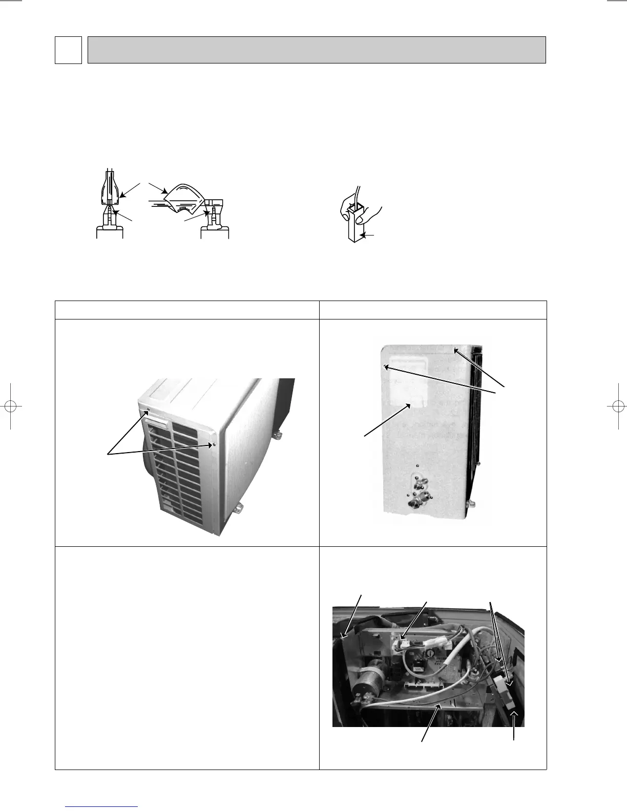
1. Removing the cabinet
(1) Remove the screws of the cabinet.
(2) Hold the down of the cabinet on the both side and remove
the cabinet.
2. Removing the deicer P.C. board
(1) Remove the service panel and the cabinet.
(2) Disconnect all the connectors and the terminals on the
deicer P.C. board.
(3) Remove the deicer P.C. board.
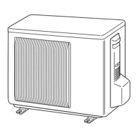
11-1. MUH-GA50VB
OUTDOOR UNIT
Photo 1
Photo 3
Photo 2
Screws of
the cabinet
Screws
of the
cabinet
Service
panel
Terminal blocks
Relay panel
Deicer
P.C. board
Screw of the
relay panel
Screw of the
relay panel
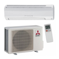
(1) Slide the sleeve and check if there is a locking lever or not.
(2) The terminal with this connector has the
locking mechanism.
1Slide the sleeve.
2Pull the terminal while
pushing the locking
lever.
1Hold the sleeve, and
pull out the terminal
slowly.
The terminal which has the locking mechanism can be detached as shown below.
There are two types ( Refer to (1) and (2)) of the terminal with locking mechanism.
The terminal without locking mechanism can be detached by pulling it out.
Check the shape of the terminal before detaching.
<"Terminal with locking mechanism" Detaching points>
Connector
Sleeve
Locking lever
OB368B-2.qxp 10.5.25 9:16 AM Page 36
 Loading...