EasyManua.ls Logo

Mitsubishi Q00JCPU User Manual

Mitsubishi Q00JCPU
976 pages
To Next Page IconTo Next Page
To Previous Page IconTo Previous Page
Page #184 background imageLoading...
Page #184 background image
3 - 86
3.9 Numeric Values which can be Used in Sequence Programs
3.9.4 Real numbers (Floating-point data)
3
SEQUENCE PROGRAM CONFIGURATION AND
EXECUTION CONDITIONS
3.9.4 Real numbers (Floating-point data)
Real number data includes the single-precision floating-point data and the
double-precision floating-point data.
The Universal model QCPU can use the double-precision floating-point data.
(1) Single-precision floating-point data
(a) Internal expression of real number data
The CPU module internal expression of received real number data is explained
below.
Real number data is expressed as shown below, using 2 word devices.
[Sign] 1.[Mantissa] 2
(exponent part)
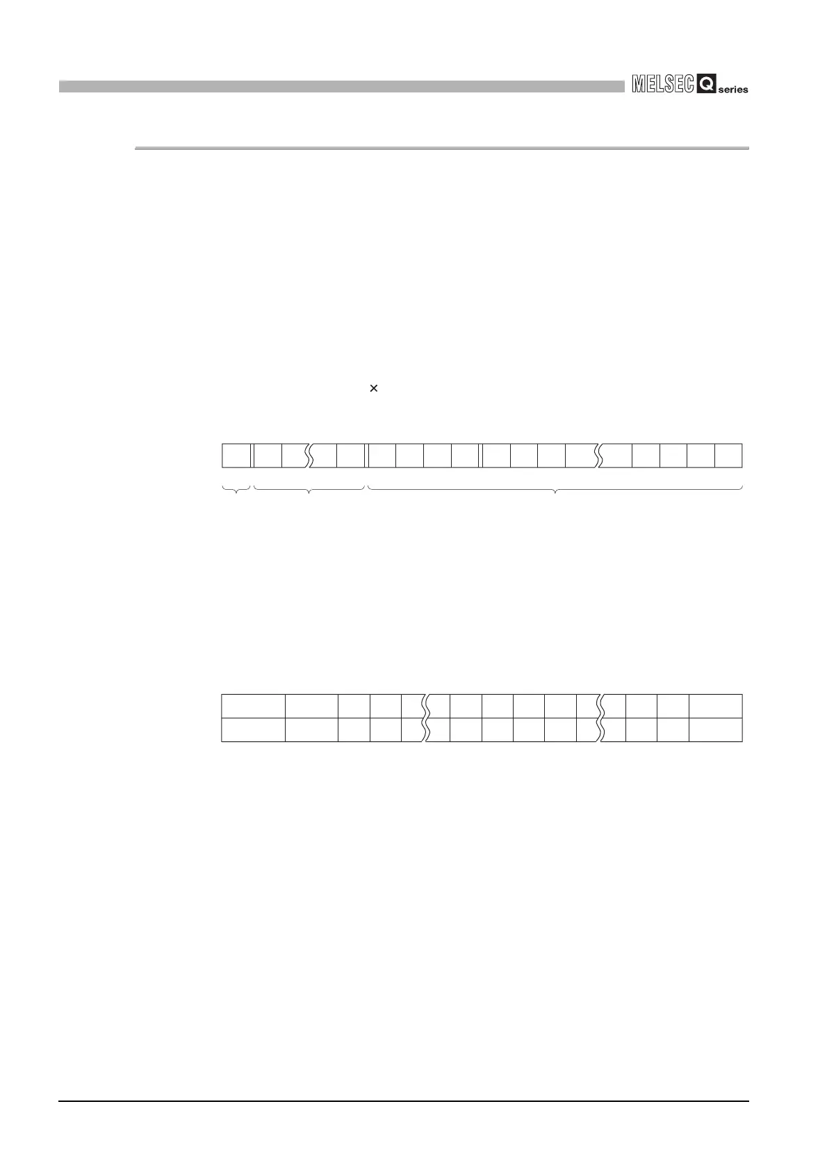
The bit configuration of internal expression for the real number data is as follows:
1) Sign
The sign is expressed at b31 as follows.
0: Positive
1: Negative
2) Exponent part
The “n” of 2n is expressed by b23 to b30, depending on the BIN value in b23
to b30.
3) Mantissa:
For a binary number “1.XXXXXX.....”, the “XXXXXX.....” portion is expressed
by 23 bits (b0 to b22).
Figure 3.69 Bit configuration of real number data
Figure 3.70 Relation between value stored in exponent part and exponent
b31 b30
to
b23 b22
to
b16 b15
to
b0
b31
b22 to b0
Mantissa (23bit)
b23 to b30
Exponent part (8bit)
Sign
b30 to b23
n
FFH
Not used
FEH
127
FDH
126
00H
Not used
02H
-125
01
H
-126
81H
2
80
H
1
7FH
0
7E
H
-1

Table of Contents

Other manuals for Mitsubishi Q00JCPU

Question and Answer IconNeed help?

Do you have a question about the Mitsubishi Q00JCPU and is the answer not in the manual?

Mitsubishi Q00JCPU Specifications

General IconGeneral
SeriesQ Series
Power Supply24 VDC
Operating Temperature0 to 55 °C
Storage Temperature-25 to 75 °C
Humidity5 to 95% RH (non-condensing)
CategoryCPU Module
Number of I/O256 points
CommunicationRS-232
Shock Resistance147 m/s2, Action time: 11 ms

Summary

QCPU

SAFETY PRECAUTIONS

Design Precautions

Installation Precautions

Wiring Precautions

DANGER

Startup and Maintenance Precautions

Startup and Maintenance Precautions

Precautions for starting up and maintaining the PLC and its modules.

CHAPTER1 OVERVIEW

CHAPTER2 PERFORMANCE SPECIFICATION

CHAPTER3 SEQUENCE PROGRAM CONFIGURATION AND EXECUTION CONDITIONS

3.1 Sequence Program

Describes sequence programs created using sequence instructions.

3.3 Settings for Creation and Execution of Multiple Sequence Programs

Explains settings for creating and executing multiple sequence programs.

3.4 Operation Processing

Explains the operation processing of the CPU module.

3.5 RUN, STOP, PAUSE Operation Processing

Explains the CPU module's three operation statuses: RUN, STOP, and PAUSE.

3.7 Data Clear Processing

Explains how to clear CPU module data and latch data settings.

3.8 I/O Processing and Response Lag

Explains I/O processing modes and response lags.

CHAPTER4 I/O NUMBER ASSIGNMENT

4.3 Installing Extension Base Units and Setting the Number of Stages

Explains how to install extension base units and set stage numbers.

4.4 Base Unit Assignment (Base Mode)

Explains base unit assignment in Auto mode and Detail mode.

4.5 Definition of I/O Number

Explains I/O numbers indicating addresses for ON/OFF data between CPU and other modules.

4.6 Concept of I/O Number Assignment

Explains the concept of I/O number assignment.

4.7 I/O Assignment Using GX Developer

Describes the I/O assignment using GX Developer.

CHAPTER5 MEMORIES AND FILES USED IN CPU MODULE

5.1 Basic Model QCPU

Explains memory configuration and storable data for the Basic model QCPU.

CHAPTER6 FUNCTIONS

6.1 Function List

Lists the functions of the CPU module.

6.2 Constant scan

Explains executing programs at a constant time interval regardless of program scan time.

6.3 Latch Function

Explains how to retain device data even after power off or reset.

6.6 Remote Operation

Explains changing operating status of the CPU module externally.

6.8 Error Time Output Mode Setting

Explains setting output behavior (clear/hold) upon CPU module stop error.

6.9 Hardware Error Time PLC Operation Settings

Explains setting CPU module operation mode (stop/continue) upon intelligent function module hardware error.

6.11 Monitor Function

Explains reading program, device, and intelligent function module status using GX Developer.

6.12 Writing in Program during CPU Module RUN

Explains writing programs or files while CPU module is in RUN status.

6.17 Self-diagnostics Function

Explains the self-diagnosis function for detecting CPU module errors.

CHAPTER7 COMMUNICATION USING BUILT-IN ETHERNET PORTS OF CPU MODULE

7.2 GX Developer/GOT Connection

Describes the setting method for connecting the Built-in Ethernet port QCPU with GX Developer and/or GOT.

CHAPTER8 COMMUNICATION WITH INTELLIGENT FUNCTION MODULE

CHAPTER9 PARAMETERS

CHAPTER10 DEVICE EXPLANATION

CHAPTER11 CPU MODULE PROCESSING TIME

CHAPTER12 PROCEDURE FOR WRITING PROGRAM TO CPU MODULE

12.2 High Performance Model QCPU, Process CPU, Redundant CPU, Universal Model QCPU

Explains items to be examined for program creation for these CPU modules.

Related product manuals