2-14 MAINTENANCE
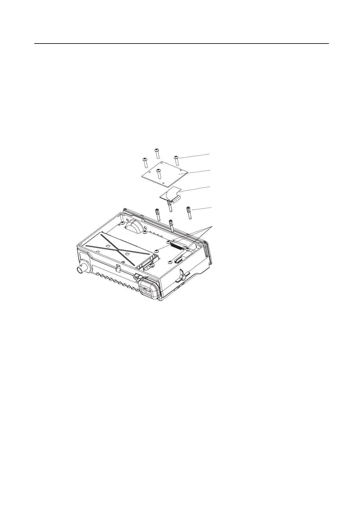
7.4 Option Board Installation
1. Follow the disassembly procedure in paragraphs 6.1 to 6.3.
2. Remove and discard the 4xM3 screws holding the main pcb and replace with the 4 spacers
provided. Torque the spacers to 1.13Nm (10 lbs.in).
3. Insert the jumper flex into the connector on the option board. Notice the orientation of the
right-angle flex circuit.
4. Insert the other end of the jumper flex into the connector on the main pcb.
5. Fold the flex circuit under the option board.
6. Position the option board over the spacers and retain using the 4xM2 screws provided.
Figure 2-13 Option Board Installation
7. With the option board correctly in place, the main shield and top cover can be assembled as
detailed in paragraph 7.1.1 steps 11 to 13.
Spacers
Flex
Option Board
M2 Screws
4xM3 screws
(replaced by spacers)
 Loading...