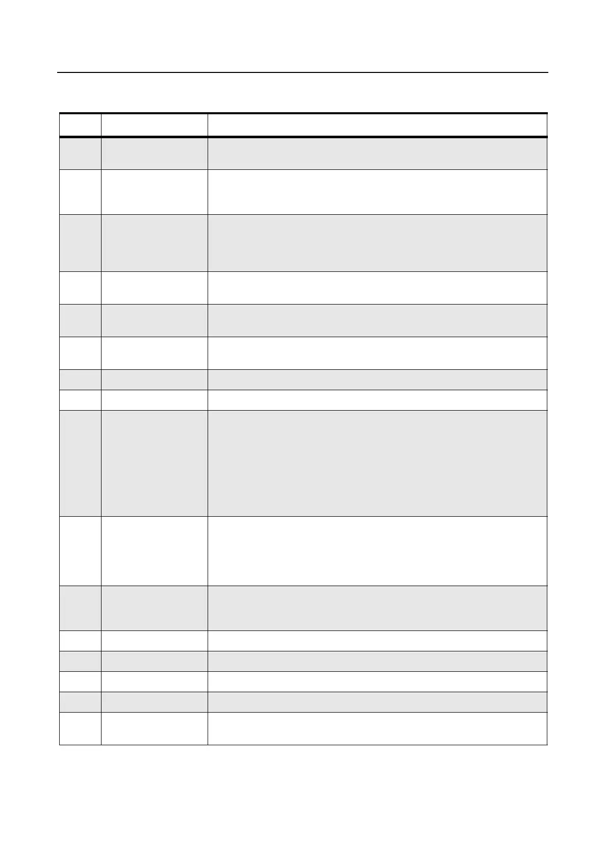
6-4 ACCESSORIES & CONNECTOR PIN FUNCTIONS
2.0 Accessory Connector Pin Function
Pin Function Description
1 External Speaker (-) Connect external 8 or 4 ohms speaker to pin 1 and 16.
Caution: Bridge-type output. Neither pin 1 or 16 is grounded.
2 External Mic Audio Input impedence:500 ohms
80 mV rms at 1 kHz for 60% deviation.
This path is enabled when external mic PTT is keyed.
3 External Mic PTT Put this pin low (less than 0.66 Vdc) to key transmitter and enable
external mic audio path. This path is pulled low via a diode when front
panel mic PTT is pulled low to allow sensing of mic PTT by accessory.
This pin pulled high to 3.3 Vdc via 3.3k ohms
4 Programmable
Output
Defaults to External Alarm. Provides an active high to 13.8 Vdc battery
supply. maximum current: 0.25 amps.
5 Flat_TX_Audio Input Input impedance: Greater than 35k ohms. The nominal input level is 150
mV rms for 60% deviation.
6 Bus+ Serial Communication Interface. On MDC and P/L radios only, this pin
can be configured as a general purpose input by removing resistor R421.
7 Ground Used as ground.
8 Programmable I/O Input or output depending on dealer programming.
9 Emergency Input When connecting the Emergency Footswitch between pin 9 and 7, the
radio will sense the connection upon Power-up.
Shorting this pin to Ground by pressing the switch when the radio is OFF,
turns ON the radio in Emergency Mode.
Shorting this pin to Ground by pressing the switch when the radio is ON,
activates Emergency Mode.
To turn OFF a radio that was turned ON by Emergency Footswitch (ON/
OFF knob in OFF position) turn knob to ON and then to OFF position.
10 Ignition Sense For optional 3-wire ignition control, connect this pin to the vehicle
ignition-controlled voltage source for ignition-controlled radio ON/OFF.
To resume NON ignition state, remove the battery connection for 10
seconds; remove the ignition connection from this pin and re-connect the
battery connections.
11 Receive Audio
Output
Programmable (using CPS in the RX Audio Type): 660mV rms (de-
emphasized/muted) or 330mV rms (non de-emphasized muted.
Minimum load resistance: 5k ohms
12 Programmable I/O Input or Output
13 Switched B+ (Switched Battery Voltage) 13.8Vdc (500mA max.) when radio is ON
14 Programmable I/O Input or Output
15 Internal Speaker Connect to internal speaker (+) and by internal jumper to pin 16
16 External Speaker (+) Connect external 8 or 4 ohms speaker to pins 1 and 16.
CAUTION: Bridge type output. Neither pin 1 nor 16 is grounded.
 Loading...