2-2 THEORY OF OPERATION
2.2 Receiver Back End
The IF signal from the crystal filter enters the IF amplifier which provides 20 dB of gain and feeds
the IF IC at pin 1. The first IF signal at 44.85 MHz mixes with the second local oscillator (LO) at
44.395 MHz to produce the second IF at 455 kHz. The second LO uses the external crystal Y301.
The second IF signal is amplified and filtered by two external ceramic filters (FL303/FL302 for
12.5KHz channel spacing and FL304/FL301 for 25KHz channel spacing). The IF IC demodulates
the signal by means of a quadrature detector and feeds the detected audio (via pin 7) to the audio
processing circuits. At IF IC pin 5, an RSSI signal is available with a dynamic range of 70 dB.
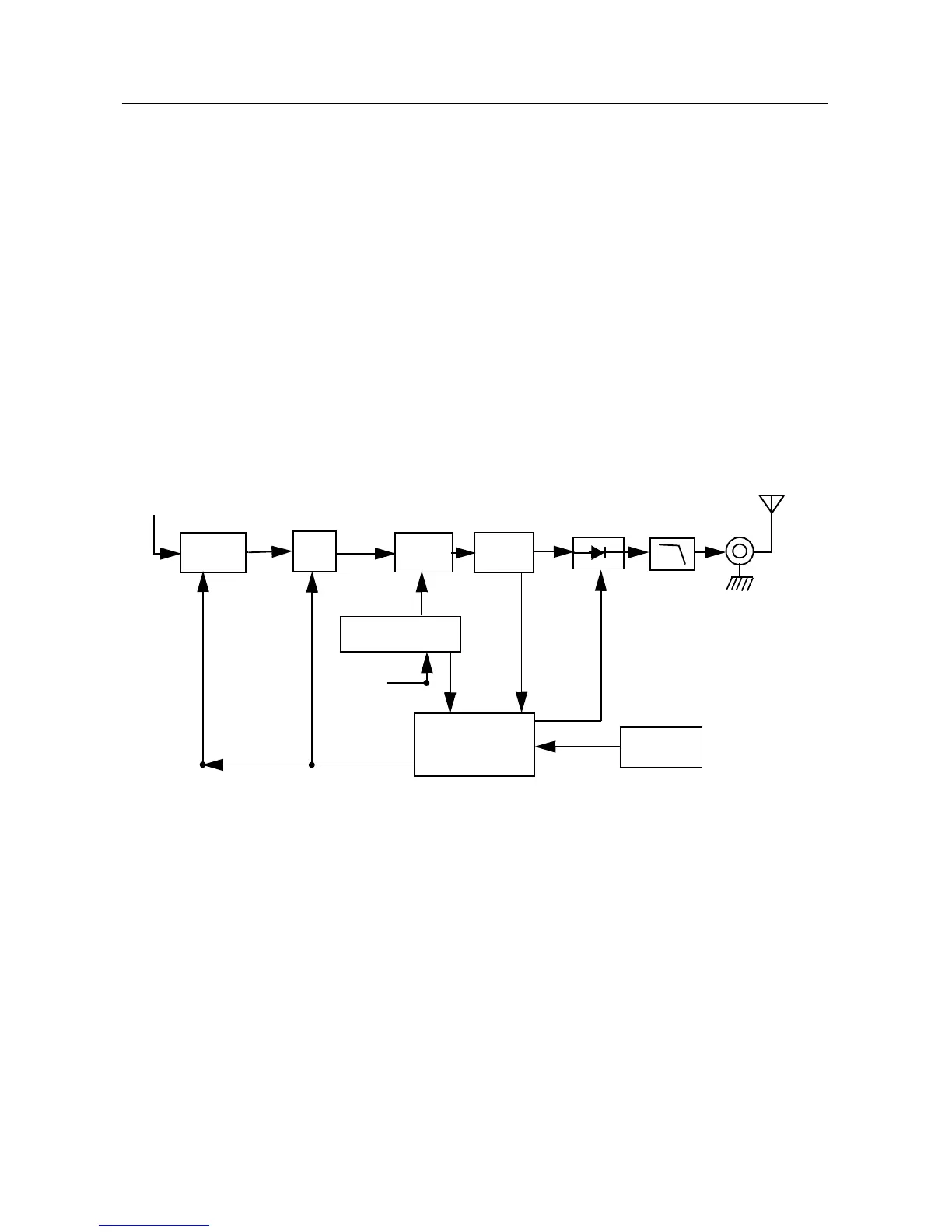
3.0 VHF Transmitter Power Amplifier (136-162 MHz)
The radio’s 25W PA is a three-stage amplifier used to amplify the output from the TX_INJ to the
antenna port. All three stages utilize LDMOS technology. The gain of the first stage (U101)and the
second stage (Q105) is adjustable and is controlled by pin 7 of U103-2 via U103-3 and U102-1. It is
followed by an LDMOS final stage Q100.
Figure 2-2 VHF Transmitter Block Diagram
Devices U101, Q105 and Q100 are surface mounted. Two screws with Belleville washers provide
direct pressure ensuring good thermal contact between both the driver and final stage, and the
chassis.
3.1 First Power Controller Stage
The first stage (U101) is a 20dB gain integrated circuit containing two LDMOS FET amplifier stages.
It amplifies the RF signal from the VCO (TX_INJ). The output power of stage U101 is controlled by a
DC voltage applied to pin 1 from the op-amp U103-3, pin 8. The control voltage simultaneously
varies the bias of two FET stages within U101. This biasing point determines the overall gain of
U101 and therefore its output drive level to Q105, which in turn controls the output power of the PA.
Loop
Pin Diode
Antenna
Switch
RF Jack
Antenna
Harmonic
Filter
Coupler
PA-Final
Stage
From VCO (TX_INJ)
Controlled
Stage
Bias
Temperature
Sense
SPI BUS
ASFIC_CMP
PA
PWR
SET
PA
Driver
Controller
U103-2
Forward
 Loading...