3-4 TROUBLESHOOTING CHARTS
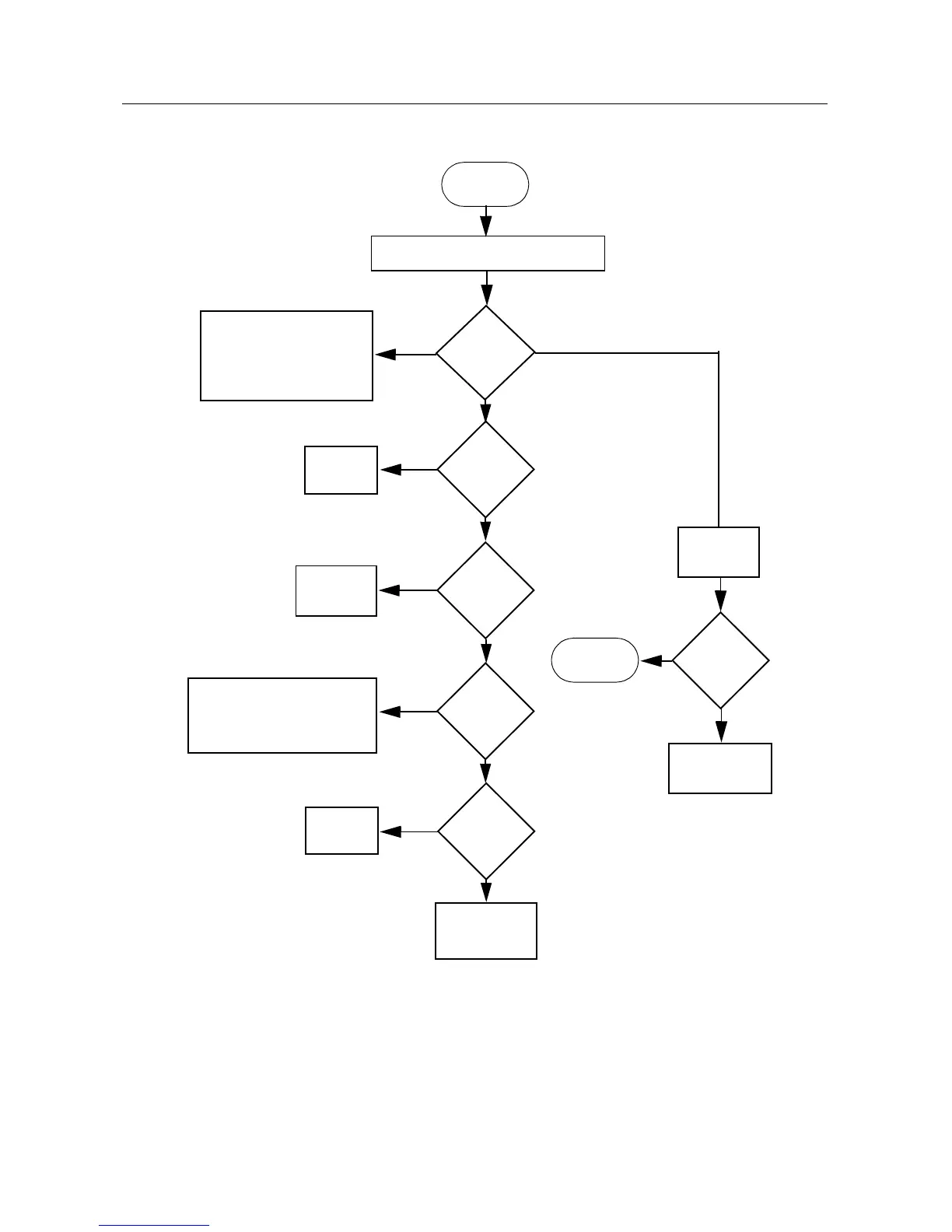
2.0 Troubleshooting Flow Chart for 25W Transmitter (Sheet 1 of 3)
START
Yes
No
Check components between
Q100 and RF output,
Antenna Switch D104,
D103, VR102 and Q106 be-
fore replacing Q100
No or too low power when keyed
Current
increase when
keyed?
Check power settings, tuning
& components between U103
Pin 3 and ASFIC Pin 6 before
replacing ASFIC
Control
Voltage at
TP150
=>1.5V?
Check PA
Stages
>1.0A
Voltage U103
pin 5 =
4.62V?
U103 Pin 3
<2.6V
U100 Pin 3
>2Vdc
Check 9.3V
Regulator
U501
Yes
Yes
No
No
Yes
Check
U103
Check forward
Power Sense
Circuit
No
Short U100
Pin 3 to
ground
Voltage at
TP150 rises?
Check PA
Stages
Check Forward
Power Sense
Circuit
Yes
No
>430mA & <1.0A
<500mA
 Loading...