Receive Signalling Circuits 2-21
9.4 Handset Audio
Certain handheld accessories have a speaker within them which require a different voltage level
than that provided by U502. For these devices HANDSET AUDIO is available at control head
connector J2 pin18.
The received audio from the output of the ASFIC CMP’s digital volume attenuator is routed to U505
pin 2 where it is amplified. This signal is routed from the output of the op-amp U505 to J2-pin 18.
From the control head, the signal is sent directly to the microphone jack.
9.5 Filtered Audio and Flat Audio
The ASFIC CMP output audio at U504-pin 39 is filtered and de-emphasized, but has not gone
through the digital volume attenuator. From ASFIC CMP U504-pin 39 the signal is routed via R5034
through gate U509-pin 12 and AC coupled to U505-pin 6. The gate controlled by ASFIC CMP port
GCB4 selects between the filtered audio signal from the ASFIC CMP pin 39 (URXOUT) or the
unfiltered (flat) audio signal from the ASFIC CMP pin 10 (UIO). Resistors R5034 and R5021
determine the gain of op-amp UU505-pin 6 for the filtered audio while R5032 and R5021 determine
the gain for the flat Audio. The output of U505-pin 7 is then routed to P1 pin 11 via DC blocking
capacitor C5003. Note that any volume adjustment of the signal on this path must be done by the
accessory.
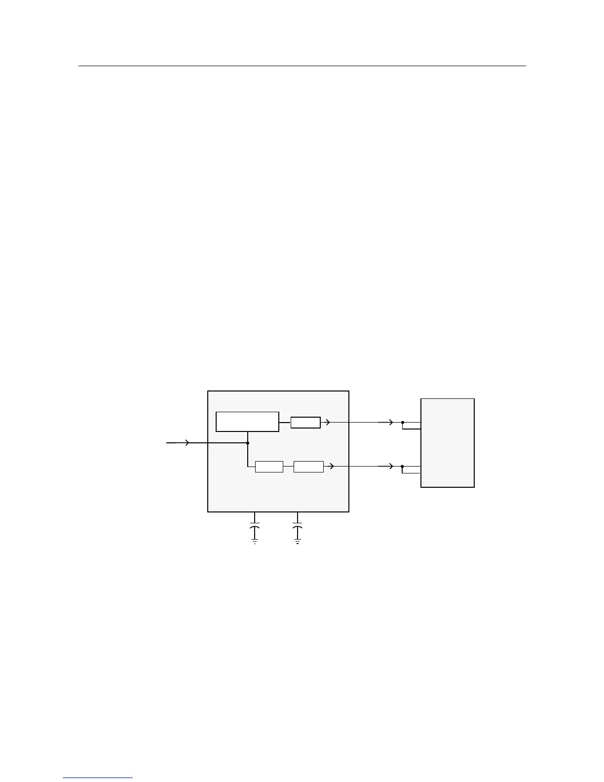
10.0 Receive Signalling Circuits
Figure 2-10 Receive Signalling Paths
10.1 Sub-Audio Data (PL/DPL) and High Speed Data Decoder
The ASFIC CMP (U504) is used to filter and limit all received data. The data enters the ASFIC CMP
at input DISC (U504 pin 2). Inside U504 the data is filtered according to data type (HS or LS), then it
is limited to a 0-3.3V digital level. The MDC and trunking high speed data appear at U504-pin 19,
where it connects to the µP U403 pin 80.
DET AUDIO
DISCRIMINATOR AUDIO
FROM RF SECTION
(IF IC)
19
18
25
2
82
80
DISC
PLCAP2
LSIO
HSIO
DATA FILTER
AND DEEMPHASIS
LIMITER
FILTER
LIMITER
ASFIC_CMP
U504
MICRO
CONTROLLER
U403
85
44
8
PLEAP
 Loading...