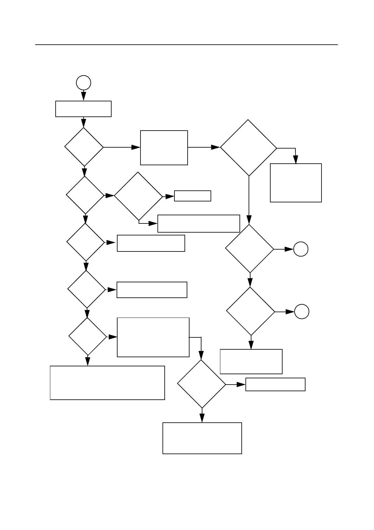
3-2 TROUBLESHOOTING CHARTS
Troubleshooting Flow Chart for Receiver for all models except those
with PCB 8486473Z04 (Sheet 2 of 2)
Q3200
collector OK?
IF signal
present?
RF
Signal
at C3306
?
RF
Signal
at C3302
?
RF
Signal
at R3313
?
IF Signal
at C3200?
Check filter between
C3302 & C3306; program
filter to schematic test freq
and check varactor
voltages.
Check Q3721, U3701
(pin 48) voltages
and U3711
Check harmonic filters L3531 & L3532,
C3532 and ant. switches D3521, D3551,
L3551, R3551,C3551, C3552, L3552.
Is R5
present
?
Trace IF signal
from C3200 to
Q3200. Check for
bad XTAL filter.
No
RF
Signal
at T3301
?
No
No
No or
Inject RF into J3501
Are
varactor
voltages
OK
?
No
Yes
Check RF amp
(Q3302) Stage.
Check filter between
C3313 & T3301.
Yes
Check T3301, T3302, CR3301,
R3321, R3322, R3320
Yes
1st LO O/P
OK?
Locked?
Yes
Check FGU
Yes
No
Yes
Yes
Check for 2.9
VDC
No
No
No
Check U404 voltage. U404
can be selected by MCU
before replacing U404.
Check varactor filter.
No
Yes
Yes
Yes
A
A
B
weak RF
Before replacing
U3220, check
U3220 voltages;
trace IF signal
path.
 Loading...