5 Installation and commissioning
60 BA5831400-00 EN
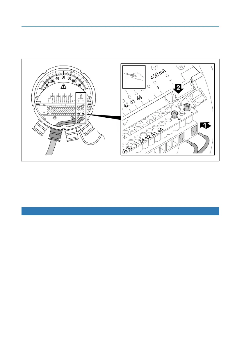
To connect the analog sensor, proceed as follows:
1. Connect the wires for the sensor to the terminal strip at the + and – termi-
nals.
Figure44: Connecting the analog sensor
2. Connect an evaluation unit with driving input (12...30VDC) or, if neces-
sary, an additional power supply (24VDC).
5.4.8 Connecting cable glands/NPT adapters
NOTICE
Damage to the device!
If you do not use any locking screws, or if you use the wrong ones, the
IP55 degree of protection cannot be guaranteed. Dirt or moisture can pene-
trate and cause damage to the device.
► Seal unneeded cable glands/NPT adaptors with suitable locking screws
and gaskets to ensure the IP55 degree of protection.
 Loading...