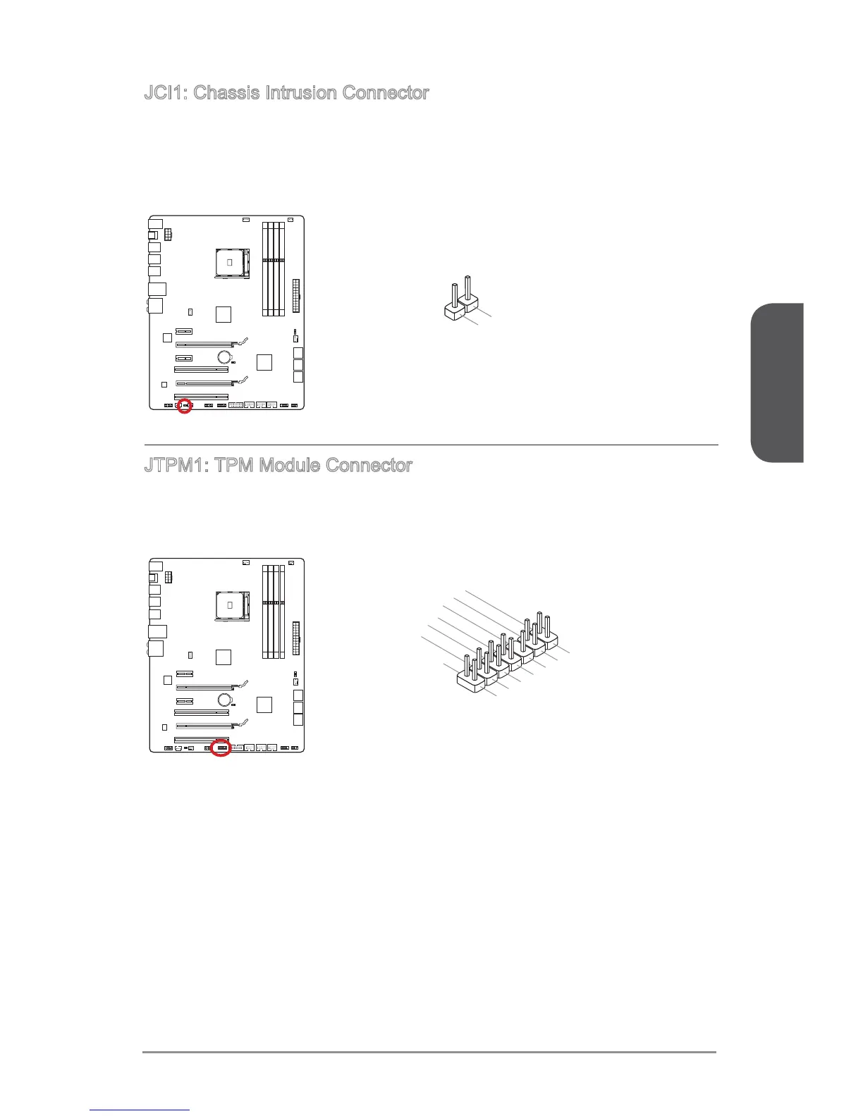
JCI1: Chassis Intrusion Connector
This connector connects to the chassis intrusion switch cable. If the computer case is
opened, the chassis intrusion mechanism will be activated. The system will record this
enter the BIOS utility and clear the record.
2.Gruond
1.CINTRU
JTPM1: TPM Module Connector
This connector connects to a TPM (Trusted Platform Module). Please refer to the TPM
security platform manual for more details and usages.
10.No Pin
14.Ground
8.5V Power
12.Ground
6.Serial IRQ
4.3.3V Power
2.3V Standby power
1.LPC Clock
3.LPC Reset
5.LPC address & data pin0
7.LPC address & data pin1
9.LPC address & data pin2
11.LPC address & data pin3
13.LPC Frame
 Loading...