EasyManuals Logo
Home>MSI>Motherboard>B650M PROJECT ZERO

MSI B650M PROJECT ZERO User Manual

MSI B650M PROJECT ZERO
428 pages
To Next Page IconTo Next Page
To Previous Page IconTo Previous Page
Page #139 background imageLoading...
Page #139 background image
33
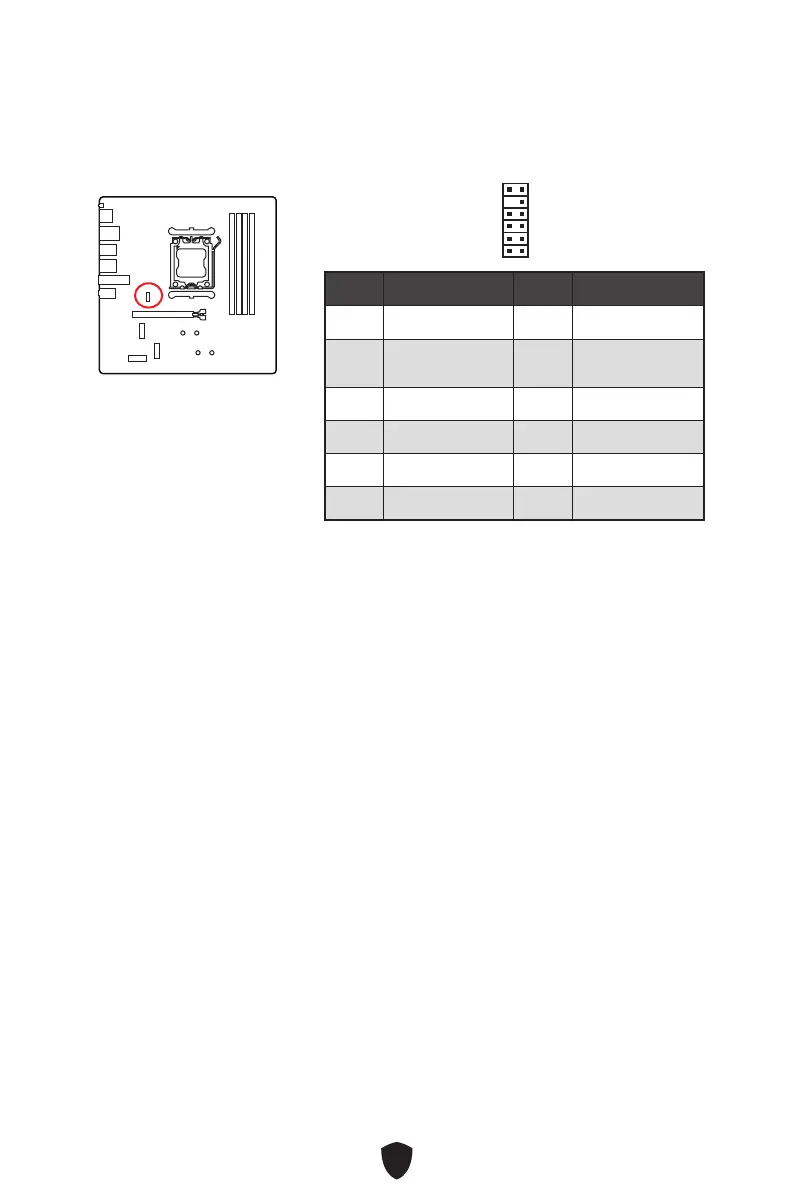
JTPM1 : Connecteur de module TPM
Ce connecteur est relié à un module TPM (Trusted Platform Module). Veuillez vous
référer au manuel du module TPM pour plus d’informations.
Broche Nom de signal Broche Nom de signal
1 SPI Power 2 SPI Chip Select
3
Master In Slave Out
(SPI Data)
4
Master Out Slave In
(SPI Data)
5 Reserved 6 SPI Clock
7 Ground 8 SPI Reset
9 Reserved 10 No Pin
11 Reserved 12 Interrupt Request
1
2
12
11
Important
Le connecteur JTPM est situé sous le dissipateur WMOS. Avant d’installer le module
TPM, retirez le dissipateur.

Table of Contents

Questions and Answers:

Question and Answer IconNeed help?

Do you have a question about the MSI B650M PROJECT ZERO and is the answer not in the manual?

MSI B650M PROJECT ZERO Specifications

General IconGeneral
BrandMSI
ModelB650M PROJECT ZERO
CategoryMotherboard
LanguageEnglish

Related product manuals